Led indicators – Westermo MR-200 User Manual
Page 12
12
6615-2202
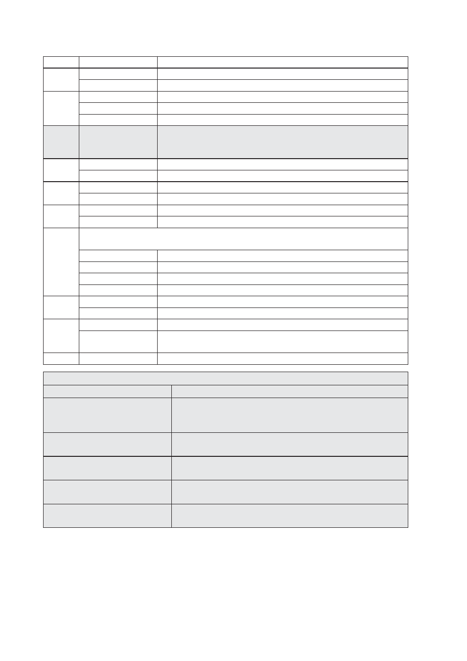
LED Indicators
LED
Status
Description
PWR
ON
In service
OFF
Out of service
LAN
ON
Network connection on LAN port
OFF
No connection on LAN port
Flash
Transmit or recive data on LAN port
GSM
This indicator is connected directly to the GSM module within
the router and operates as described in the GSM Status Indicator
Functions table below.
NET
ON
A wireless network has been detected
OFF
No wireless network has been detected
SIM
ON
A valid SIM card is installed in the unit
OFF
No valid SIM card is installed in the unit
DAT
Flash
Data is being transferred over the wireless network
OFF
No data is being transferred over the wireless network
Signal
The three indicators labelled SIGNAL illuminate to indicate the GSM signal strength as
follows:
None illuminated
< -113 dBm (effectively no signal)
1 LED illuminated
>= -112 dBm and <= –87 dBm (weak)
2 LED’s illuminated
>= -86 dBm and <= –71 dBm (medium)
3 LED’s illuminated
>= -70 dBm and <= –51 dBm (strong)
GPS
ON
GPS option fitted and has been successfully configured by the unit
OFF
GPS option not fitted or not successfully configured
DTE
ON
Terminal connected to the serial port and the DTR signal is on
OFF
No connection on serial port Data is transmitted or received on
the serial port
Flash
Data is transmitted or received on the serial port
GSM Status Indicator Functions
OFF
GSM module is in SLEEP or Charge-only mode.
600 ms ON / 600 ms OFF
No SIM card inserted or no PIN entered, or network search
in progress, or ongoing user authentication, or network login
in progress.
75 ms ON / 3 s OFF
Logged on to network (monitoring control channels and user
interactions), no call in progress.
75 ms ON / 75 ms OFF / 75 ms
ON / 3 s OFF
One or more GPRS contexts activated.
Flashing
LED is On when data packets were exchanged in GPRS online
mode during the last second.
ON
Connected to remote party or exchange of parameters while
setting up or disconnecting call.
Reset switch
This is located on the underside of the unit near the front. Pressing the switch gently with the tip of
a pen or other suitable implement will generate a hardware reset.
Refer to page 15 (restoring factory defaults).
It is important to allow the MR-2xx to complete the restore procedure. DO NOT press the reset
button again or power cycle the unit for at least 2 minutes.