Connections – Westermo ODW-610-F1 User Manual
Page 12
Advertising
12
6651-22601
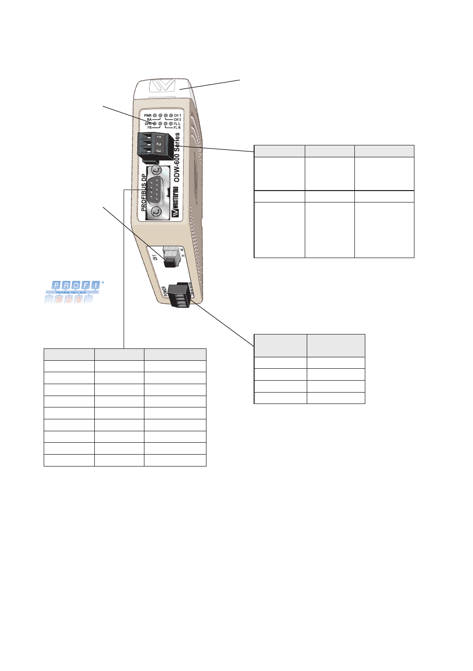
DIP-switches accessible under lid
(for details see page 14-15)
LED Indicators
(for details
see page 13)
FX(Fibre)
(for details
see page 11)
Connections
Power
screw terminal
Status
screw terminal
PROFIBUS DP
(RS-485)
D-sub
9-position Direction Description
No. 1
–
–
No. 2
–
–
No. 3
In/Out
RxD/TxD-P
No. 4
Out
CNTR-P
No. 5
–
DGND
No. 6
Out
VP
No. 7
–
–
No. 8
In/Out
RxD/TxD-N
No. 9
–
–
3-position Direction Description
No. 1
NO
Contact with
C when link is
in operation
No. 2
C
Common
No. 3
NC
Open
(no contact
with C) when
fibre link is in
operation
4-position
marking
Description
No. 1
–Voltage
No. 2
+Voltage A
No. 3
+Voltage B
No. 4
–Voltage
Advertising
This manual is related to the following products: