Start up guide, Hints – Westermo ODW-610-F1 User Manual
Page 17
17
6651-22601
Start up guide
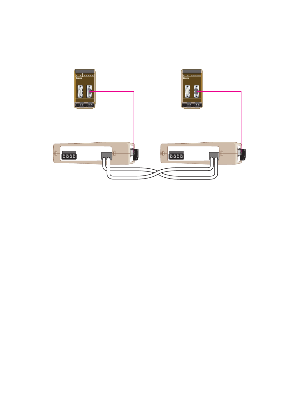
Follow the steps below to get the unit up and running in a simple application.
… Use the factory DIP-switch settings.
… Connect The fibre link between the both units.
… Connect the power supply to both ODW-610-F1.
• The Fibre link should be in operation, indicated by active CH1 LED.
… Connect the PROFIBUS DP connectors between both ODW-610-F1 and PROFIBUS
units configured to be units in the PROFIBUS DP network.
• The PROFIBUS DP will be in operation and the data rate should have been
identified, indicated by BA LED.
… The point to point application is up and running.
Hints
… If the distance is long it may be necessary to adjust the bus parameter Slot time, the
monitoring time (t
Bit
) of the sender of frame for acknowledgement of recipient, at
configuration of the PROFIBUS DP master.
… If the time between transferred PROFIBUS DP frames is long, it may be neccessary to
allow a longer time of interruption in receiving frames, using DIP-switches.
… If disturbances in the PROFIBUS DP network, result in missed frames, it may be
necessary to allow a number of consecutive faulty frames before the bus is out of
operation, using DIP-swithes.
POWER
CH 1
COM +VA +VB COM
POWER
CH 1
COM +VA +VB COM
TX
RX
TX
RX
PROFIBUS DP master
Fibre Optic
PROFIBUS DP
PROFIBUS DP
PROFIBUS DP slave