Westermo ODW-610-F1 User Manual
Page 8
8
6651-22601
Functionality and status indication
At power on, all LED's will be active during an initiation sequence followed by an auto-
matic initiation of the optical fibre link. The alarm will be set until the fibre optical link is
in operation and ready to transfer PROFIBUS DP data.
Data frames are transferred over the fibre optical link as long as the link is in operation
and the data rate has been detected.
When the fibre optical link is out of operation, it will be indicated by a local alarm, and
this will set the alarm output. When the link returns to operations mode, the alarm will
rest automatically.
The Bus active (BA) LED is set if data frames are received on the electrical PROFIBUS
DP port and the data rate is detected, independently of the status on fibre optical link.
Redundant power supply, galvanic isolated (2 kVAC) to other ports
ODW-610-F1 should be supplied with safety extra low voltage (SELV). It is designed to
operate permanently over a wide input range and provided with two independent inputs
for enhanced redundancy if either supply fails.
9-position D-sub PROFIBUS DP connector
The pin assignment for the connector is in compliance with PROFIBUS standard
EN 50 170.
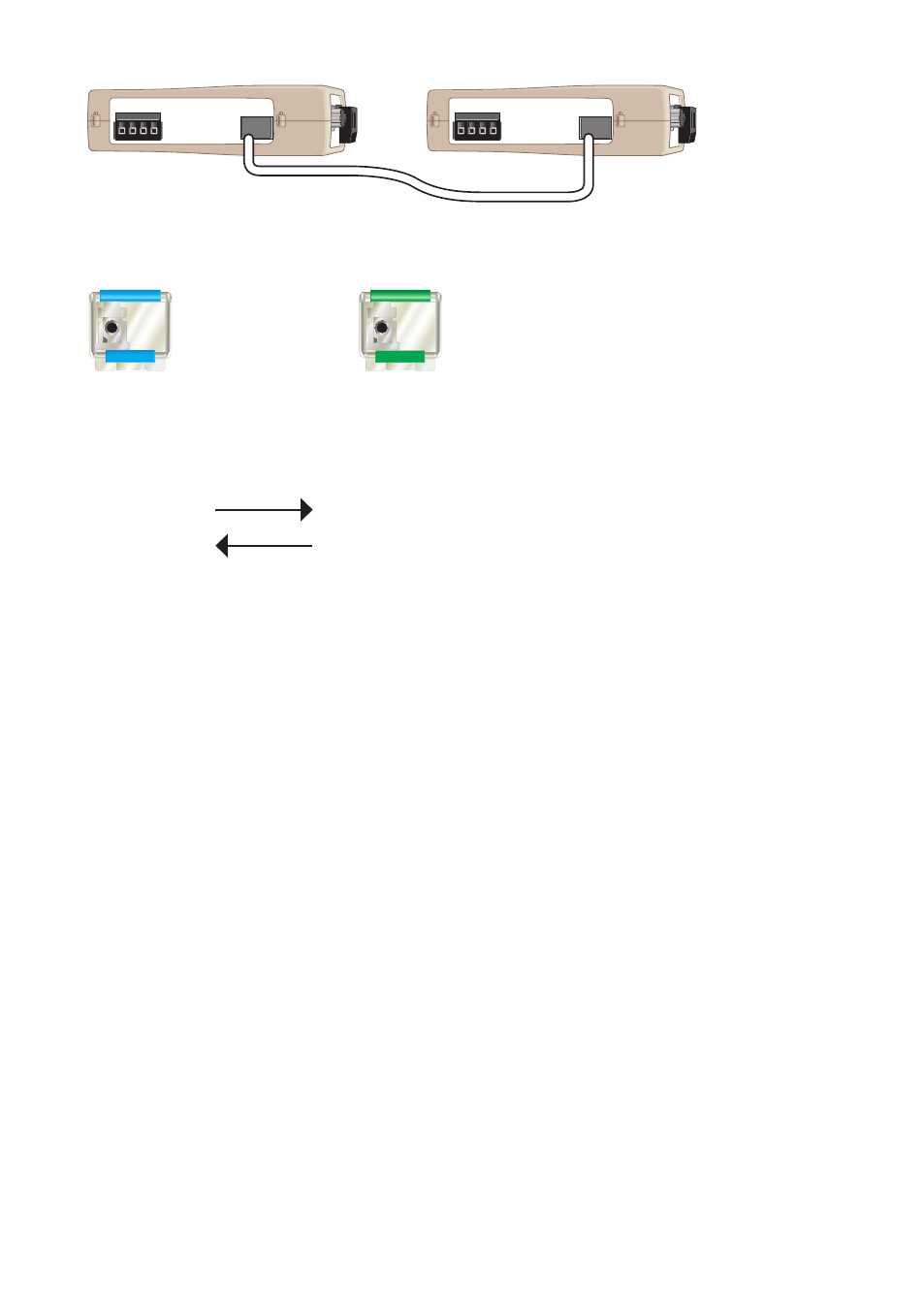
Note! The bi-di transceivers must always be used in pair, see example:
TX 1310 nm
RX 1310 nm
RX 1550 nm
TX 1550 nm
POWER
CH 1
COM +VA +VB COM
POWER
CH 1
COM +VA +VB COM
TX/
RX
TX/
RX
Fibre optical connection
at point to point communication (Bi-di transceiver)
Bi-di transceiver, TX 1310 nm,
RX 1550 nm.
Bi-di transceiver, TX 1550 nm,
RX 1310 nm.