Westermo ODW-620-F1 User Manual
Page 17
17
6651-22621
Configure the ODW-620-F1s. Using the factory DIP-switch settings, set:
…
S1: CTS always active or RTS/CTS control.
…
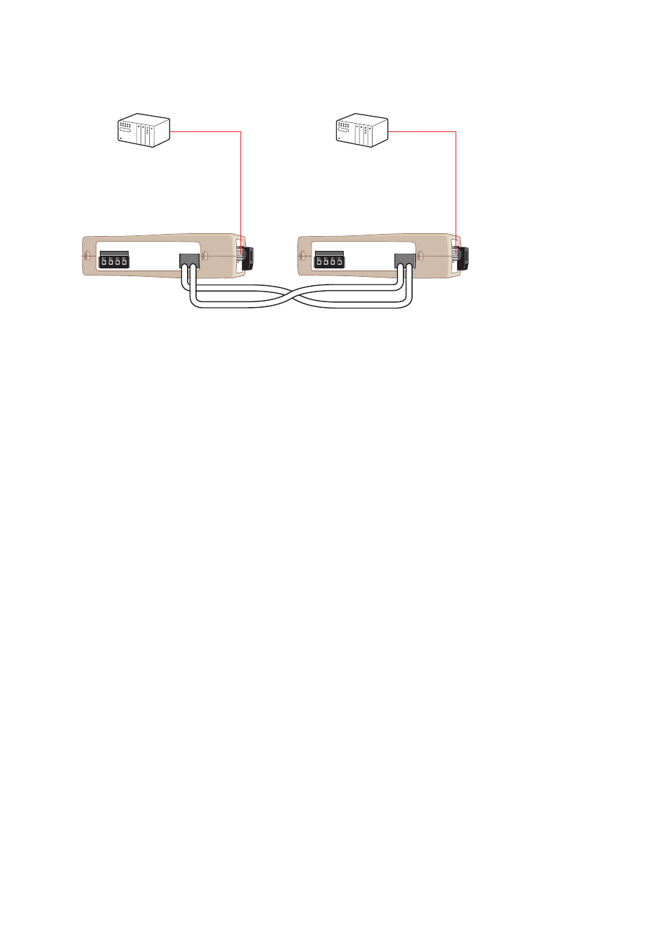
Connect The fibre link between the ODW-620-F1s.
…
Connect the power supply to both ODW-620-F1s.
…
After a few seconds the fibre link should be in operation, indicated by an active CH1
…
LED.
Connect the serial cables from PLC master and slave to respective ODW-620-F1s.
…
Frames from PLC master that are correctly received the ODW-620-F1 should be indi-
…
cated by flashing TD LED.
Frames that are received via the fibre link will be transmitted to the PLC slave
…
and indicated by flashing RD LED.
Replies from slave to master will be transferred and indicated in the opposite way.
…
The point-to-point application is up and running.
…
POWER
CH 1
COM +VA +VB COM
POWER
CH 1
COM +VA +VB COM
TX
RX
TX
RX
Start up guide, point-to-point application
Follow the steps below to get the unit up and running in a simple application.
Master
Slave