3 indicators 6.3.1 led indicators – Westermo RD-48 User Manual
Page 20
20
6153-2004
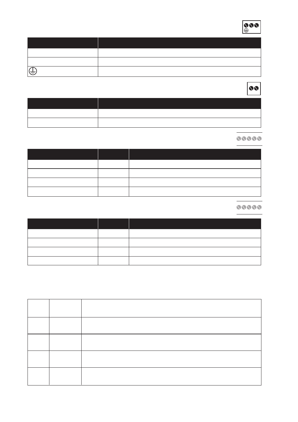
6.2.1 Power (RD-48 HV)
6.2.2 Power (RD-48 LV / RD-48 LV TEMP)
6.2.3 Line A RS-422/485
6.2.4 Line B RS-422/485
3-pos screw terminal
Description
L
Power AC line / Power DC
N
Power AC neutral / Power DC
Power AC protective earth
2-pos screw terminal
Description
No. 1
Power DC –
No. 2
Power DC +
4-pos screw terminal
Direction Description
No. 1
In
R+ RS-422 receiver
No. 2
In
R– RS-422 receiver
No. 3
In/Out
T+ RS-422/485 transmitter/receiver
No. 4
In/Out
T– RS-422/485 transmitter/receiver
4-pos screw terminal
Direction Description
No. 1
In
R+ RS-422 receiver
No. 2
In
R– RS-422 receiver
No. 3
In/Out
T+ RS-422/485 transmitter/receiver
No. 4
In/Out
T– RS-422/485 transmitter/receiver
6.3 Indicators
6.3.1 LED indicators
PWR LED on
Internal power correct
LED off
No internal power
RDA
LED on
Received data line A
LED off
No data line A
RDB
LED on
Received data line B
LED off
No data line B
BLA
LED on
Blocking line A
LED off
No blocking line A
BLB
LED on
Blocking line B
LED off
No blocking line B
N
L
1
2
5
6
7
8
9
4
3
2
1
5
6
7
8
9
4
3
2
1