Owner’s manual – X-Treme Audio XTDP User Manual
Page 3
2.2 Key Features
• Minimal signal path design
• Sonically superb ADC / DAC combination thanks to a carefully
matched pairing of the best devices from Burr Brown and Wolfson
• Newly released family of Analog Devices SHARC DSP
• Extended bandwidth; 96kHz sampling frequency provides for a
nominally flat response to 40kHz.
• Parameter knob and LCD provide rapid, user-friendly control
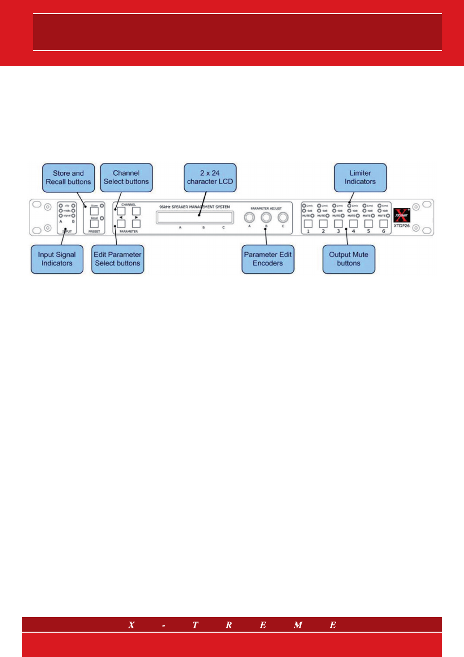
3. Front Panel
3.1 Input Signal Indicators
A set of three pairs of LEDs indicate signal present, +4dBu and input
clip for each channel. The signal present LEDs operate at approxi-
mately –40 dBu, giving a useful indication of even relatively low input
signal levels. The +4 dBu LEDs are intended to show nominal oper-
ating level and can also be useful for setting system gain structure.
Clip LEDs warn the user of input overload and operate at +19 dBu.
3.2 Preset Store and Recall
These controls provide access to the 45 presets stored within the
device. Pressing the store button allows the user to name a preset
and choose which memory location it will be held in. Pressing the
store button again completes the process. The Recall function op-
erates in a similar way, pressing the recall button allows the user to
select which preset they require, pressing the button for a second
time, then confirming, recalls the new DSP settings. Note that pre-
sets cannot be stored or recalled when Secure mode is activated.
3.3 Parameter Knobs
Three velocity sensitive parameter knobs are used to adjust param-
eters shown on the display. Up to three parameters at a time are
displayed on the screen. The parameter name is shown above the
parameter value in each of the three screen sections. The parameter
knobs have a fixed association with the screen sections; the right-
most parameter knob adjusts the rightmost parameter and so on.
3.4 Output Signal / Limiter Indication
Two LEDs are provided for each output channel. These show the
signal level related to the limiter threshold. The yellow LED will light
up when the signal is 6 dB below the threshold, while the red warn-
ing LED will light up when the limiter threshold is reached.
3.5 Mute Buttons and Status LEDs
Each output has a Mute button and associated mute status LED.
Pressing the button turns the mute on and off.
Note that the mute buttons do not function when the Secure mode
is activated.
3.6 Secure Button
A momentary button is fitted behind the rear panel, between the
output XLR and the RS232 port. When activated, this will disable
all the front panel controls so they cannot affect the signal path,
making the unit secure against tampering. When in secure mode,
the indicators still operate normally.
Note that the communications port is still active in Secure mode.
3.7 Text Display
Preset, channel, parameter and status information is shown on the
2 x 24 character text display. In most screens the currently selected
channel is displayed on the upper line and the edit parameter on
the lower line. To simplify the display and enhance safety, some
parameters or parameter pages are omitted when not relevant.
3.8 Channel Select Buttons
The currently selected channel is displayed on the top left hand
corner of the LCD. Pressing the channel buttons scrolls through
the available input and output channels and finally through the util-
ity functions and back to the default screen. If operating a stereo
linked preset, the channel name will indicate the channel pairing.
For example ‘A+B’ means both input A and B parameters. The
name of the output will be shown briefly at the top of the display
when stepping onto an output.
3.9 Edit Parameters Select Buttons
The currently selected edit parameter page is displayed on the bot-
tom left corner of the LCD. Pressing the edit select buttons moves
through the available parameters for the current input or output.
3/13