Xtdp controllers – X-Treme Audio XTDP User Manual
Page 4
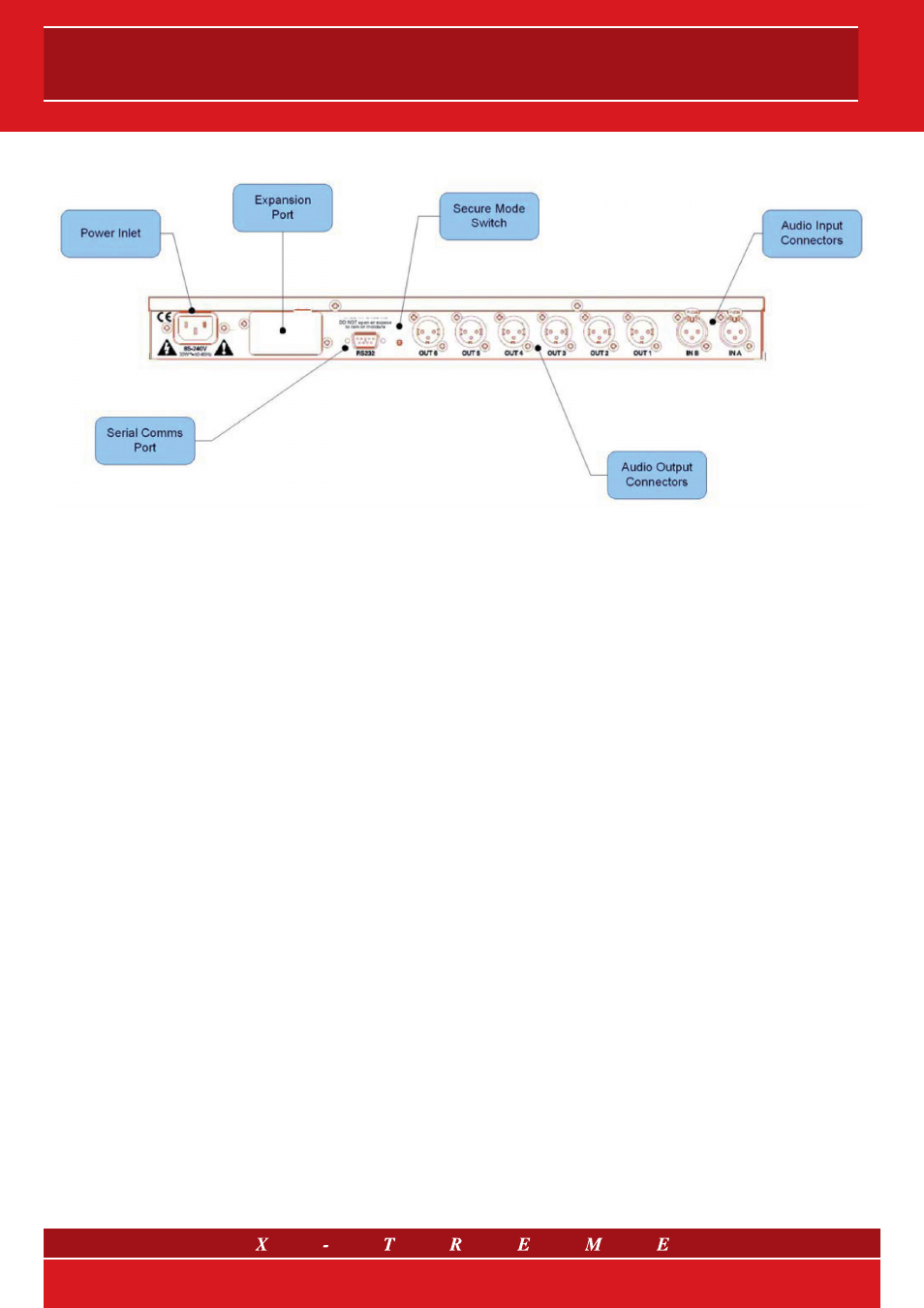
4. Rear Panel
4.1 Power Inlet
The X-Treme XTDP units should be connected to a suitable mains
electricity supply using the cable supplied. The processor has a
switch mode power supply that is capable of operating with a no-
minal mains voltage of 85V to 240V, 50/60Hz without re-configu-
ration.
4.2 XT-NET Port
This is the port - with RJ45 connection - for the remote controlling
of a network with many other devices (XT-NET); everything is done
from only one external PC using the software Network Contoller.
4.3 Audio Input Connectors
All audio connections are fully balanced and wired pin-1 ground,
pin-2 hot & pin-3 cold. The two inputs have pin-1 connected di-
rectly to the chassis and supply the signal processing chains. If an
unbalanced source is used, a connection should be made betwe-
en the pin-3 ‘cold’ signal and the ground connection of the unba-
lanced source.
4.4 Audio Output Connectors
The processed outputs are impedance balanced, and wired pin-1
ground, pin-2 hot and pin-3 cold. An unbalanced input may be
driven by connecting pin-3 ‘cold’ signal to the ground connection
of the unbalanced destination input. Note that output pin-1’s are
ground lifted at audio frequencies but connected to ground at RF
for good EMC performance. The intention being that the amplifiers
the processor is driving should be responsible for the grounding of
their input cable shields.
4.5 Expansion Port and Serial Comms Port
X-Treme XTDP controllers may be controlled - one by one - entirely
from another device, typically a Personal Computer, running an ap-
plication that is compliant with the ObCom standard: the Network
Controller. Connection will normally be made to the controller via
this serial port connector (RS232). This port is also used for upda-
ting the firmware in the unit. Note that the communications port
is NOT disabled when the front panel is made secure using the
Secure button.
4/13