Owner’s manual – X-Treme Audio XTDT User Manual
Page 6
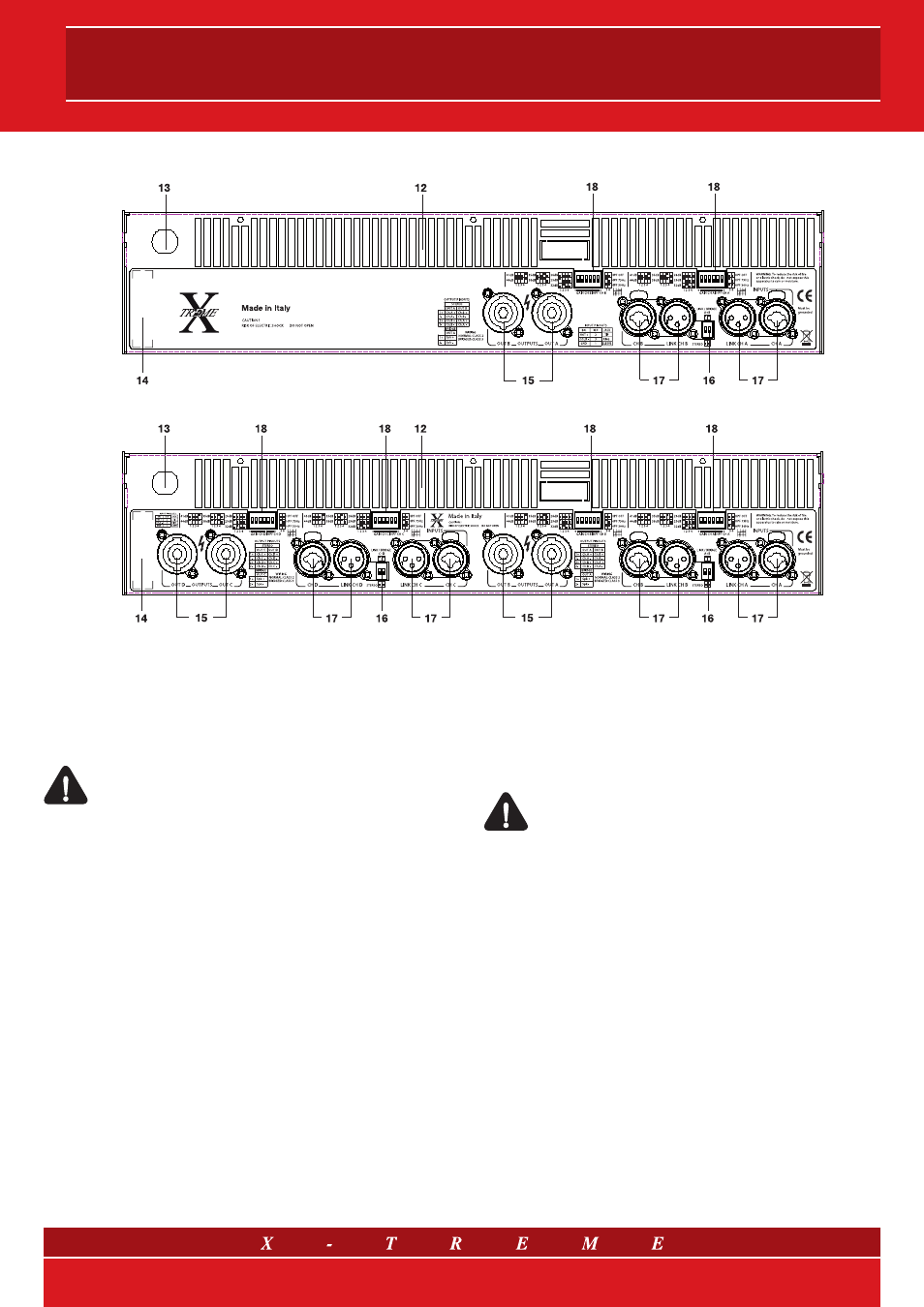
3.4 Rear Panel: controls and connectors
fig.4 a) Back panel mod. XTDT3200 and XTDT3800
fig.4 b) Back panel mod. XTDT4800F and XTDT6000F
12) Fan discharge grids
The fan of the cooling system creates an airflow with front/back
directions. The air for cooling the amplifier is taken from the open-
ing on the front side and it is then discharged through the opening
on the back.
Warning: do not obstruct these openings.
13) A.C. Mains cable
Make sure that the cable is undamaged and that the connecting
plug has earth connection.
14) S.N. tag
Every unit has a tag showing: model, power consumption and
serial number.
15) Speakon output connectors
There is a connector for every channel when operating in stereo or
parallel mode. For operating in bridge use Neutrik Combo
©
con-
nector (refer to fig. 5, 6, 7).
16) Switch for mode setting
Switch to set the usage mode (refer to drawings 5, 6 and 7).
17) Input connectors
Combo
©
connectors (female XLR with 6.3 mm jack), a connector
for every channel for balanced or unbalanced inputs.
Warning: noises such as buzzing or disturbance on the
loudspeakers may occur when installing wiring next to
dimmer, motors, etc. Balanced connections reduce con-
siderably such noises.
18) HPF and Gain Switch
A 6-position DIP switch to set different gain values and High Pass
Filter for each different channel.
6/14