Xtdt amplifiers – X-Treme Audio XTDT User Manual
Page 9
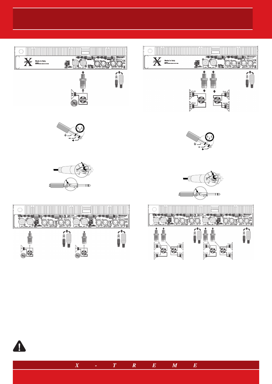
fig. 6 a) Bridge Mono Mode mod. XTDT3200 and XTDT3800
6.3mm (1/4-inch) TRS, XLR
shield
inverting
non-inverting
Balanced Connection
Unbalanced Connection
jumper
jumper
6.3mm (1/4-inch) TRS, XLR
fig. 6 b) Bridge Mono Mode mod. XTDT4800F and XTDT6000F
• Parallel inputs (Link)
The parallel mode is enabled when the Link switches are set to
position “ON”. In parallel mode, the inputs of both channels are
connected and receive the same signal. The input signal should
be connected to Ch A or Ch B for 2 Ch. amplifiers, and also Ch
C or Ch D for 4 Ch. units. Both input connectors Combo
©
can be
used. Level attenuators work independently, it is therefore possible
to set a different level for every channel. The loudspeakers are linked
to the speakon output connectors A and B (2 Ch. - see fig. 7 a) or A
and B, C and D (4 Ch. - see fig. 7 b)
Please make sure that only the inputs are connected in parallel. Nev-
er connect the positive output terminals on earth or parallel.
Warning: always unplug the Link switches when running
the amplifier for Bi-amping.
fig. 7 a) Parallel Inputs (Link) mod. XTDT3200 and XTDT3800
6.3mm (1/4-inch) TRS, XLR
shield
inverting
non-inverting
Balanced Connection
Unbalanced Connection
jumper
jumper
6.3mm (1/4-inch) TRS, XLR
fig. 7 b) Parallel Inputs (Link) mod. XTDT4800F and XTDT6000F
9/14