Owner’s manual, User instruction – X-Treme Audio XTDT User Manual
Page 8
5. User instruction
5.1 Maximum power consumption
Check whether there is enough power to supply the amplifier
(refer to the data at the end of this manual). Please ensure that
the voltage of the network complies with the instructions found at
the back of the amplifier. Maximum power consumption is limited
solely through the internal fuses.
Warning: before any audio connection keep in mind that
the regular procedure is to turn off the amplifier and to
unplug it from the mains, and set the volume tuners to the
minimum during start up.
5.2 Cooling
Pay particular attention to the ventilation/cooling conditions of the
amplifier. An internal system of forced airflow, by a variable speed
fan, allows cooling of the dissipators from the heat generated by
power parts. The airflow is directed from the front panel to the
back panel of the amplifier, which means that the air is drawn in
from the front and is discharged through the back opening.
Pay particular attention to leave enough space in front of the am-
plifier to allow the air to go in and enough space at the back to
allow it to come out. If the amplifier is installed in a rack strand,
make sure that there is enough air clearance: air should easily flow
through the amplifier and meet no resistance.
5.3 Settings
Make sure that the equipment is turned off before setting it ac-
cording to your needs.
It is also possible to set the amplifier for the following functions:
• Gain
One of the main advantages of XTDT amplifiers is the sectable
input gain for each channel, thanks to proper DIP switch that are
placed in the rear pannel. The user is able to calculate the right
Sensitivity value starting from the maximum output voltage and,
obviously, the driven load.
In particular:
V
MAX
= (PxZ)
1/2
, where P = power and Z = impedance;
V
MAX
(dBu)
= 20 log V
MAX
/ V
0
, where V
0
= 0.775 V;
Sensitivity (dBu) = V
MAX
(dBu) - Gain (dB).
• Selectable filter for low frequencies
Your amplifier is equipped with an HPF filter that can be selected
for every channel. To set the cutting frequencies use DIP switches
that are placed in the rear pannel of the amplifiers; the cutting
frequencies available are 30 or 75 Hz. When the filter is disabled,
the amplifier will still be protected by the input DC.
• Stereo mode (standard)
When using stereo mode every channel operates independently
and its input attenuators control the respective level.
The minimum recommended load for running in stereo is 2 Ohm
per channel for
XTDT3200 and XTDT3800 and 4 Ohm per chan-
nel for
XTDT4800F and XTDT6000F (please refer to technical
specifications).
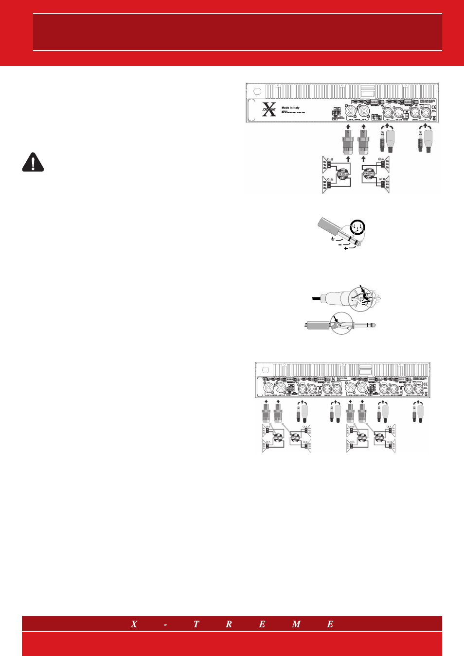
The input signal can be connected by using Combo
©
connectors
cabled on the back panel. The loudspeakers are linked to the out-
put connectors speakon A-B (C-D) (refer to fig. 5).
fig. 5 a) Stereo Mode mod. XTDT3200 and XTDT3800
6.3mm (1/4-inch) TRS, XLR
shield
inverting
non-inverting
Balanced Connection
Unbalanced Connection
jumper
jumper
6.3mm (1/4-inch) TRS, XLR
Fig. 5 b) Stereo Mode mod. XTDT4800F and XTDT6000F
• Bridged mono mode
The bridged mono mode is enabled when the Link/Bridge switch-
es on the back panel are set to position “ON”. Using bridged
mono mode implies that A and B (2 Ch.) or A and B, C and D
(4 Ch.) are running with the same input signal, but with inverted
phases. For output power values refer to technical specifications
on paragraph 7.
For bridged mono usage a single input is required for 2 Ch. am-
plifiers (Ch A or Ch B), whereas for 4 Ch. models Ch C or Ch
D can be selected also, paying particular attention that level at-
tenuators are set to the same position (we recommend position 0
dB). To connect the signal connectors Combo
©
can be used. The
loudspeakers should be linked to the selected output connector
speakon (refer to fig. 6).
8/14