ACTi V21 User Manual
Introduction, Device overview, Step 2: mount the device
Introduction
This guide contains all the information you need to quickly setup
the Video Encoder. For detailed information on installations or
operations, please refer to the Hardware Manual and Firmware
Manual on ACTi website (
www.acti.com
).
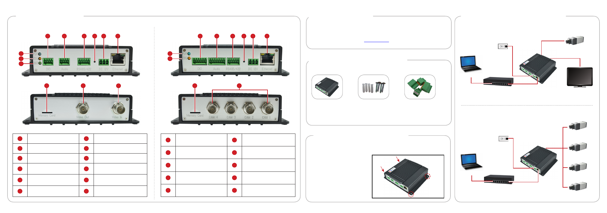
Device Overview
1
Power LED
7
Reset Button
2
Serial Port Activity LED
8
DC 12V Power Connector
3
Video In Activity LED
9
Ethernet Port
4
Digital Input / Output
Connector
10
Memory Card Slot
5
Audio Input / Output
Connector
11
Video Out Connector
6
Serial Port Connector
12
Video In Connector
The device can be directly mounted on a surface, such as walls.
Step 2: Mount the Device
Attach the 4 supplied screws
to secure the device.
V21 / V22
V23 / V24
12
11
10
4
5
7
8
9
6
2
3
1
3
4
6
7
8
5
2
1
Step 1: Unpack the Device
Check if the package comes with the following items:
Video Encoder
Mounting Screw
Pack
Terminal Blocks
•
Power
•
Audio
•
Digital Input/Output
•
Serial Communication
Step 3: Connect the Device
V21 / V22 Basic Connection Example
PC
Monitor
Power Source
(optional)
PoE Switch
Analog Camera
V23 / V24 Basic Connection Example
PC
Power Source
(optional)
PoE Switch
Analog Camera 1
Analog Camera 2
Analog Camera 3
Analog Camera 4
1
Power LED
6
Reset Button
2
Serial Port Activity LED
7
DC 12V Power Connector
3
Digital Input / Output
Connector
8
Ethernet Port
4
Audio Input / Output
Connector
9
Memory Card Slot
5
Serial Port Connector
10
Video In Connectors (1~4)
10
9