AEC VacTrac Series Conveying Systems User Manual
Page 40
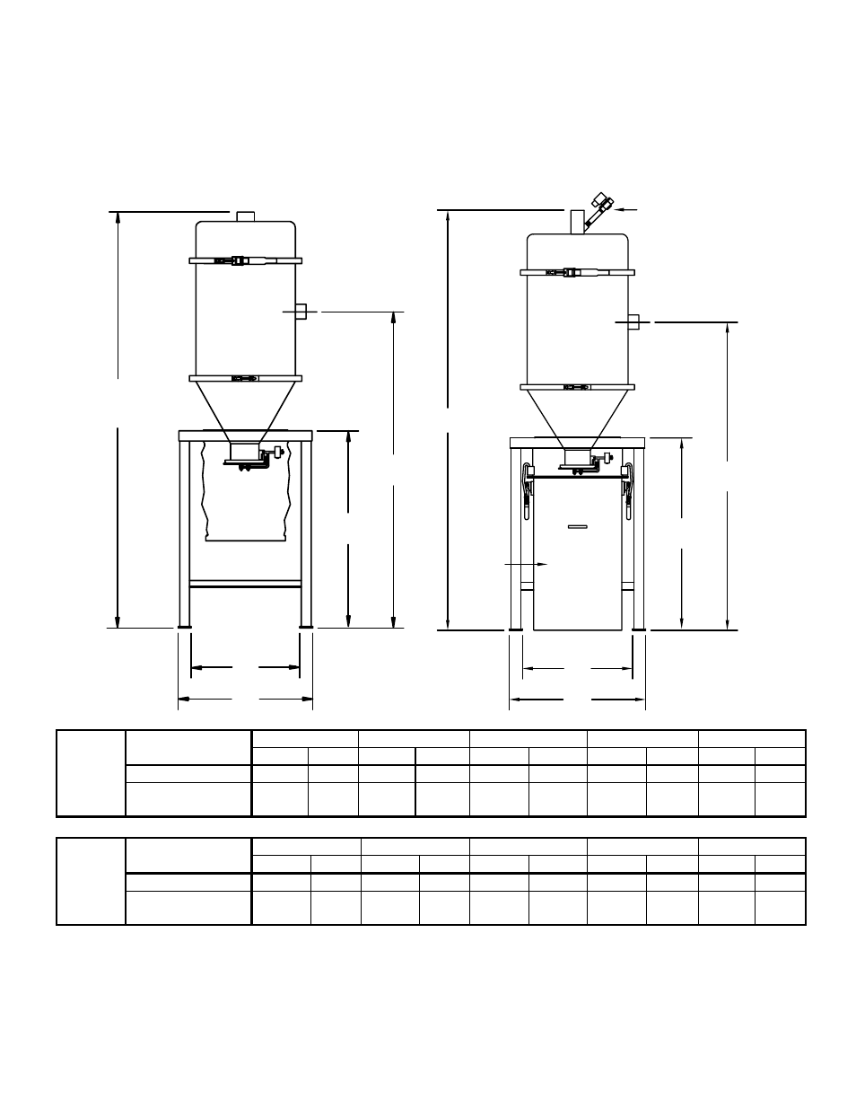
Figure 17: VFC Vortex Filter Chamber Specifications and Dimensions
B
D
A
E
C
B
C
D
A
E
Blowback
solenoid
Optional
integral
dust can
Optional
Floor A B C D E
stand
inches cm inches cm inches cm inches cm inches cm
29” (74 cm) stand
20.50”
52
67.50”
171
45.38”
115
16.50”
42
29”
74
VFC-225
Optional 45” (114
cm) stand with drum
28.50” 72 83.50” 212 61.38” 156 24.50” 62 45” 114
Floor A B C D E
stand
Inches cm inches cm inches cm inches cm inches cm
29” (74 cm) stand
26.50”
67
82.38”
209
50.38”
128
22.50”
57
29”
74
VFC-1000
Optional 45” (114
cm) stand with drum
34.50” 88 98.38” 250 66.38” 169 30.50” 77 45” 114
Note: Dimensions are approximate and subject to change without notice.
Conveying System Mechanical Components Chapter 2: Functional Description
39 of 136