Ctcss scan, Offset direction and offset frequency setup – Alinco DR-138 User Manual
Page 22
14
6
KEY OPERATIONS
UP / DOWN keys) to enter the setting and return to original status. The
T/SQ/DCS icon will remain on the display to show the current selective-
calling status. To exit, simply use the TS/DCS key and press it until the
relative status icon T/TQ/DCS disappears.
The CTCSS encoding and decoding frequencies may be set differently.
The encode setting frequency automatically relates to the decode
setting, but decode setting does not affect encode. The standard set of
50 different CTCSS tones are available. DCS encode/decode cannot be
separated. The list of selectable tones and codes is shown on Appendix
at the end of this booklet.
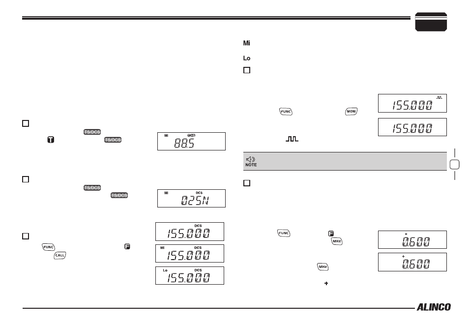
CTCSS SCAN
Repeatedly press
key until LCD
displays icons, then hold
key for 1
second to enter into CTCSS scanning. Once
finding a matching CTCSS tone, a voice will
be heard and resumes scanning after 15 seconds.
Repeatedly press
key until LCD
displays DCS icons, then hold
key for
1 second to enter into DCS scanning. Once
finding a matching DCS code, a voice will be
heard and resumes scanning after 15 seconds.
Press
key until LCD display iron,
then press
key to switch between high/
Mid/low power. The LCD appears:
None: Transmits in high power
Compander function will decrease the
background noise and enhance audio clarity.
Press
1.
key, then press
key
to turn on compander function, repeat
above operation again to turn off .
W h e n "
2.
" i c o n i s d i s p l a y e d ,
compander is active.
HIGH/MID/LOW Power switch
Compander (Decrease the background noise and ENHANCE
AUDIO CLARITY)
DCS SCAN
: Transmits in middle power
: Transmits in low power
This function is valid only among the compander-capable radios
and may worse the audio if used with non-compander ones.
Press
1.
key until the icon appears
on the LCD, then press
key, LCD
displays offset direction and offset
frequency.
Repeatedly press
2.
key to select
positive offset or negative offset.
When LCD displays "
3.
" icon, it indicates positive offset, which
Repeater receives a signal(UP-LINK) on one frequency and re-transmits
on another frequency(DOWN-LINK). The difference between these two
frequencies is called the offset frequency. If the UP-LINK frequency
higher than DOWN-LINK frequency, the direction is positive, If it is lower,
the shift direction is negative.
Offset Direction and offset frequency setup