Controls and components – Allmand Brothers I HYDRAULIC User Manual
Page 18
Advertising
18
CONTROLS AND COMPONENTS
NOTE:
COMPONENTS SHOWN ARE STANDARD. PICTURES MAY VARY WITH DIFFERENT OPTIONS.
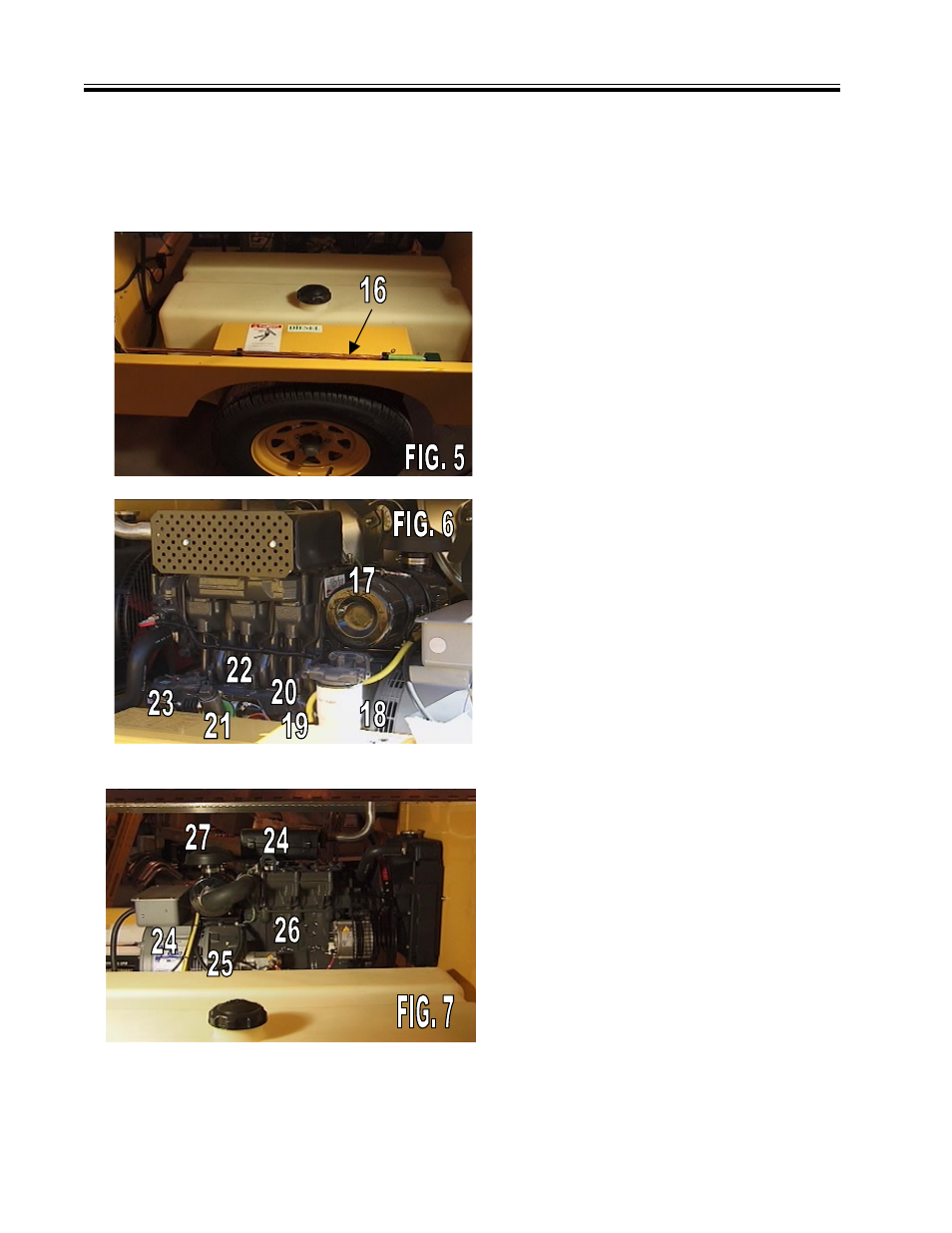
FIG. 5 GROUND ROD
16. Ground Rod
FIG. 6 ENGINE (Left Side)
17. Air Cleaner
18. Fuel Filter
19. Fuel Lift Pump
20. Fuse (10 Amp)
21. Oil fill
22. Stop Solenoid
23. Oil Filter
FIG. 7 ENGINE (Right Side)
24. Fuel Return Line
25. Fuel Suction Line
26. Starter
27. Glow Plug
Ground rod should be attached to
grounding lug with wire provided and
ground rod and then driven fully into
the earth for adequate electrical
ground, as required by local, state,
or national electrical code.
Advertising