Controls and components – Allmand Brothers ML6-8 LD User Manual
Page 18
18
CONTROLS AND COMPONENTS
NOTE:
COMPONENTS SHOWN ARE STANDARD. PICTURES MAY VARY WITH DIFFERENT OPTIONS.
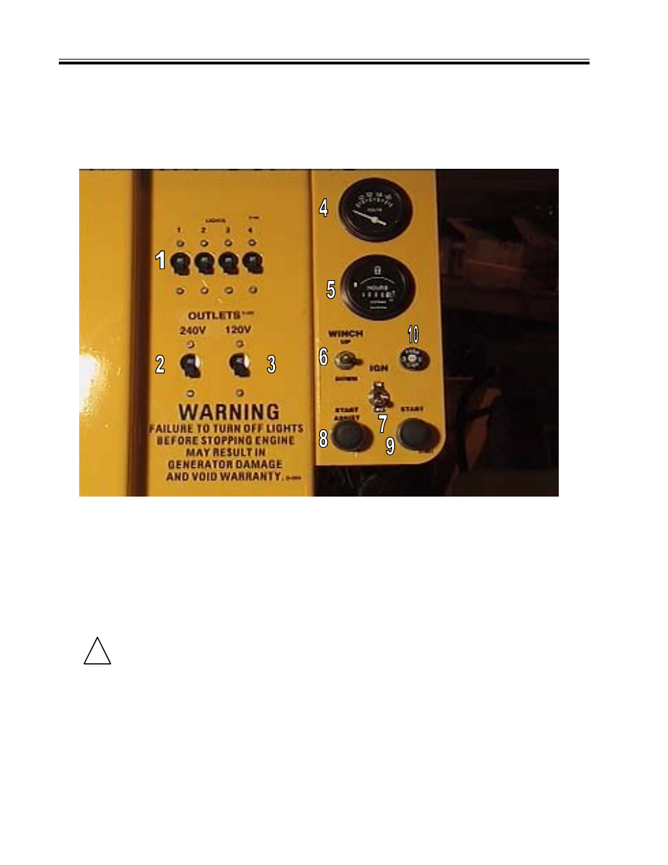
FIG. 1. A.C. CONTROL PANEL
FAILURE TO UNDERSTAND AND COMPLY
WITH SAFETY RELATED INFORMATION
AND INSTRUCTIONS MAY RESULT IN
INJURY TO THE OPERATOR OR OTHERS.
IF YOU DO NOT UNDERSTAND ANY PART
OF THIS CONTACT YOUR DEALER FOR
CLARIFICATION PRIOR TO OPERATING
EQUIPMENT.
!
SAFETY WARNING
FIGURE 1
FIGURE 2
1. Switch, Circuit Breaker (Lights 1 through 4)
2. Switch, Circuit Breaker (24OV Receptacle)
3. Switch, Circuit Breaker (120\/ Receptacles
)
FIG. 2. D.C. CONTROL PANEL
4
. Voltmeter (optional)
Indicates charging circuit voltage
5. Hour Meter
Shows total elapsed hours of engine operation.
6. Momentary Contact Switch (Electric Winch Model)
Lift up to raise and extend the tower.
Press down to Iower and fold the tower.
7. Ignition ON/OFF Switch
8. Start Assist Switch
Push to activate fuel solenoid and glow plug prior
to and while depressing start switch.
9. Start Switch
Push to start.
10. 1.5 AMP Circuit Breaker (Electric Winch Model)