Implement upper view, Hitch rear/front), Advanced settings "implement – ARAG Navigator LT User Manual
Page 18
18
ADVANCED SETTINGS
"IMPLEMENT"
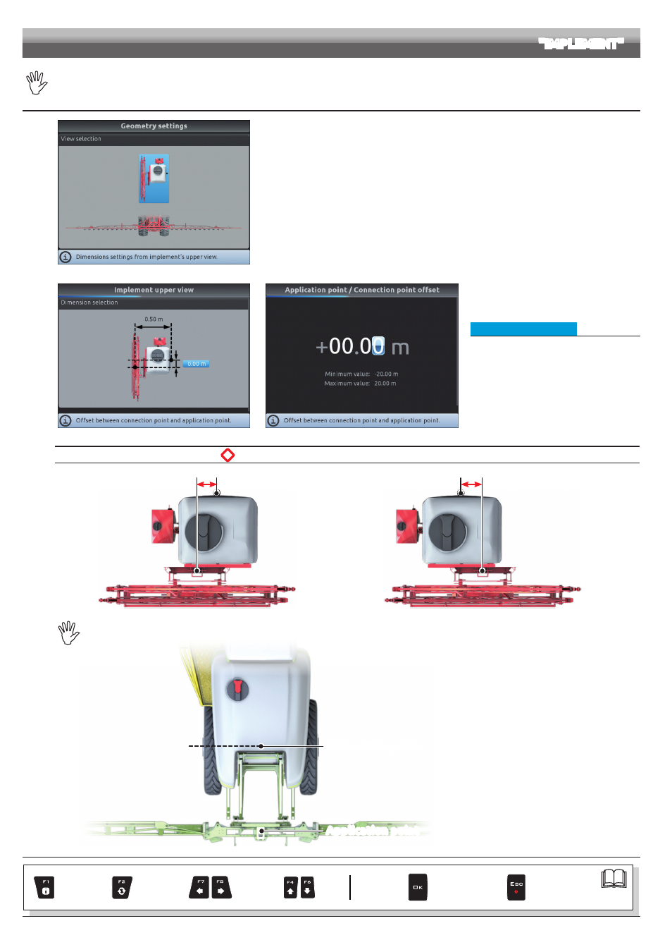
The geometry of the displayed implement depends on the selected basic settings (chap. 9).
10.1.3 Towed implement geometry settings (SYSTEM WITH 3-POINT HITCH REAR/FRONT)
Fig. 59
Enter farming machine measures:
- Press the arrow keys (UP, DOWN, LEFT, RIGHT) to move across different implement views.
- Confirm by pressing
OK
to enter setup.
Fig. 60
Fig. 61
• Implement upper view
- Press the arrow keys (UP, DOWN, LEFT,
RIGHT) to move across values: the description
of the selected value will appear on the display.
- Confirm by pressing
OK
to enter setup.
- Enter the value.
- Select and enter, one by one, all values.
*
Offset between connection point and application point
Application point
Connection point
- 1.50 m
NEGATIVE VALUES
The application point is
to the left of the
connection point.
Fig. 62
Application point
Connection point
+ 1.50 m
POSITIVE VALUES
The application point is to the
right of the connection point.
Fig. 63
THE CONNECTION POINT OF A SELF-PROPELLED MACHINE COINCIDES WITH THE REAR AXLE OF THE VEHICLE.
Connection point
Application point
Fig. 64
CONTINUES > > >
Par.
Exit the function
or data change
Confirm access
or data change
Scroll
(LEFT /
RIGHT)
Delete
selected
character
Data
increase /
decrease
Scroll
(UP /
DOWN)
Enter
selected
character