ARAG Bravo 300s series computers crop spraying - Direct connection - INSTALLATION User Manual
Page 12
12
8.3
Connection of sensors and other available functions
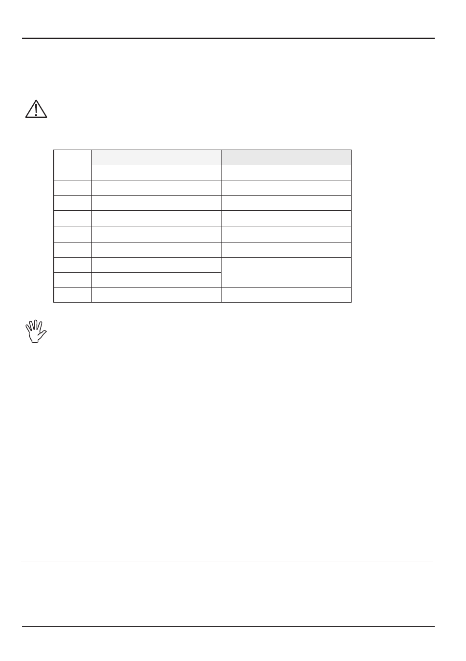
Fix the connectors to the relevant functions according to the initials indicated in your assembly
general diagram (Par. 6.1).
Harness cables are marked with a symbol denoting their functions: please see the
table for correct harness instructions.
Use ARAG sensors: use of unsuitable sensors not provided by ARAG automatically
voids the warranty.
ARAG is not liable for damages to the equipment, persons, animals or things caused
by failure to observe the above instructions.
Item
Main connection
Alternative connection
F
Flowmeter
-
g
Main valve
-
M
Pressure sensor
-
p
Control valve
-
R
Foam marker
-
S
Speed sensor
-
t
Filling flowmeter
Pump Protector
X
RPM sensor
1 ÷ 5
Section valves
-
CAUTION:
Only use the secondary input "T" if the input marked "X" is occupied by another
sensor.
Do not use the secondary input "T" if no sensor is connected to the "X" input, as the
computer will not detect the Pump Protector in this configuration.
Instructions for sensor installation are supplied with the products.
The speed sensors listed below can also be used as RPM sensors:
• inductive speed sensor
(Code 467100.086);
• magnetic speed sensor
(Code 467100.100).
- Connection of:
• flowmeter;
• pressure sensor;
• Pump Protector;
• filling flowmeter;
• RPM sensor;
• foam marker.
Tab. 3
CONTINUeS