ARAG BRAVO 300S / Orchard sprayer Direct connection Installation - Software ver. 3.x User Manual
Page 11
11
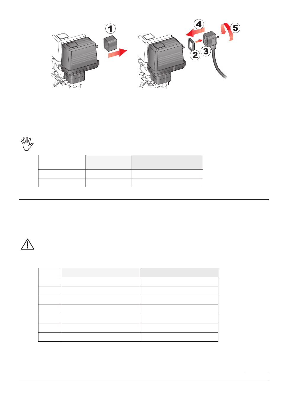
Fig. 10
Fix the connectors to the relevant valves according to the initials indicated in your assembly general
diagram (Par. 6.1 - System recommended composition).
• Remove the protection cap (
1, Fig. 10) from the electric valve.
• Place the seal (
2) onto the connector (3) and push the connector fully on (4): be careful not to
bend the contacts upon insertion on the valve.
• Tighten the screw (
5) fully home.
If there are more control panel switches than section valves, connect the wires as shown
in Table 1B.
NO. OF
SECTION VALVES
SWITCHES TO
BE USED
CABLES TO BE CONNECTED
TO SECTION VALVES
2
2 - 4
2 - 4
4
1 - 2 - 4 - 5
1 - 2 - 4 - 5
8.3
Connection of sensors and other available functions
Fix the connectors to the relevant functions according to the initials indicated in your assembly
general diagram (Par. 6.1).
Harness cables are marked with a symbol denoting their functions: please see the table
for correct harness instructions.
Use ARAG sensors: use of unsuitable sensors not provided by ARAG automatically voids
the warranty.
ARAG is not liable for damages to the equipment, persons, animals or things caused by
failure to observe the above instructions.
ITEM
MAIN CONNECTION
ALTERNATIVE CONNECTION
f
Flowmeter
-
g
Main valve
-
M
Pressure sensor
-
p
Control valve
-
s
Speed sensor
-
t
Filling flowmeter
RPM sensor or Pump Protector
X
Level sensor
-
The products are supplied with the sensor installation instructions.
The following speed sensors can also be used as RPM sensors:
• inductive speed sensor (
Code 467100.086);
• magnetic speed sensor (
Code 467100.100).
Tab. 1B
Tab. 2
CONTINUES