Installation – ARAG DIGIWOLF - Power supply version 12V DC User Manual
Page 6
6
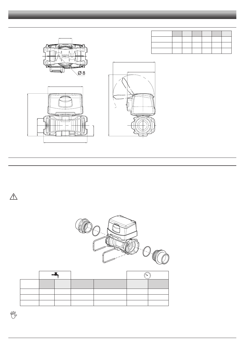
2.2
Dimensions (mm)
E
B
D
120
C
95
143
T
A
2.3
Hydraulic connections
2.3.1
Hydraulic connection for brass/fork connections
Avoid bends and constrictions before connections and on tubes.
Use ARAG connections with their suitable OR with MALE CONNECTIONS [T connections - General Catalogue (Tab. 2)].
Do not use the flowmeter at pressures greater than those listed in Table 2.
Regarding connections, use tubes and fittings properly sized for the operating pressure of the system.
CAUTION: For the implementation on already operating systems it is necessary to follow all safety rules described herein.
System assembly and start-up must be carried out by expert personnel according to the safety rules so as to ensure the same
safety level of the system the flowmeter is going to be installed in.
After connection, check for the perfect sealing of the tubes and fork connections.
CODE
l/min.
US GPM Connection Ø equivalent (inch)
Max. p
(bar)
Max. p
(PSI)
4627405A
10-200
2.6-53
T5 F
1 1/4"
20
290
4627506A
20-400
5-106
T6 F
1 1/2"
12
174
4627707A
40-800
10-210
T7 F
2"
7
130
The diameter in inches (Ø equivalent) is given only as an indication of the typical passage of the flowmeter body.
Actually, it is possible to choose different sizes depending on the fork connection used.
Fig. 8
Fig. 9
Tab. 1
CODE
A
B
C
D
E
T
4627405A
140
128
205
31
41
T5
4627506A
145
148
210
36
45
T6
4627707A
157
162
222
41
45
T7
INSTALLATION
Tab. 2