Installation – ARAG DIGIWOLF - Battery powered version User Manual
Page 6
6
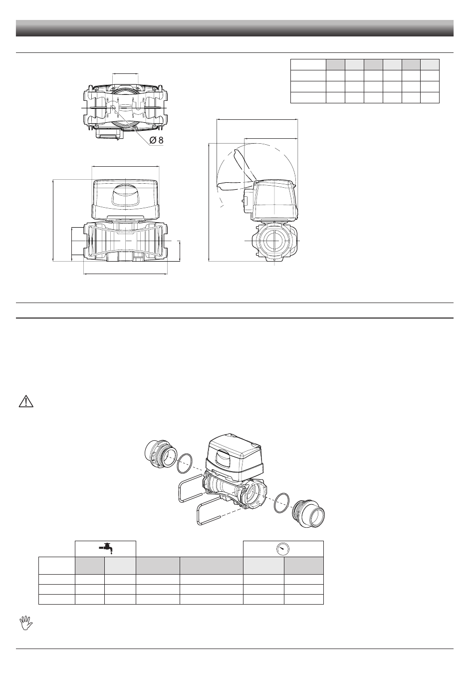
2.2
Dimensions (mm)
E
B
D
120
C
95
143
T
A
2.3
Hydraulic connections
2.3.1
Hydraulic connection for brass/fork connections
Avoid bends and constrictions before connections and on tubes.
Use ARAG connections with their suitable OR with MALE CONNECTIONS [T connections - General Catalogue (Tab. 2)].
The tubes must be able to stand a pressure of at least twice the max. operation pressure of the flowmeter (Tab. 2)
CONSIDERING THE OPERATION PRESSURES WITHIN THE SYSTEM.
Hose tail tightening must be done using the suitable metal clamps to ensure perfect mechanical sealing, even at high pressures.
The connection with threaded connectors must be done paying attention to operation pressure.
CAUTION: For the implementation on already operating systems it is necessary to follow all safety rules described herein.
System assembly and start-up must be carried out by expert personnel according to the safety rules so as to ensure the same
safety level of the system the flowmeter is going to be installed in.
After connection, check for the perfect sealing of the tubes and fork connections.
CODE
l/min.
US GPM Connection Ø equivalent (inch)
Max. p
(bar)
Max. p
(PSI)
4628405
10-200
2.6-53
T5 F
1 1/4"
20
290
4628506
20-400
5-106
T6 F
1 1/2"
12
174
4628707
40-800
10-210
T7 F
2"
7
130
The diameter in inches (Ø equivalent) is given only as an indication of the typical passage of the flowmeter body. Actually, it is
possible to choose different sizes depending on the fork connection used.
Fig. 8
Fig. 9
Tab. 1
CODE
A
B
C
D
E
T
4628405
140
128
205
31
41
T5
4628506
145
148
210
36
45
T6
4628707
157
162
222
41
45
T7
INSTALLATION
Tab. 2