Backplane diagram – Ensemble Designs 9455 3G Clean and Quiet Protection Switch User Manual
Page 11
www.ensembledesigns.com
7435 and 9455 - page 11
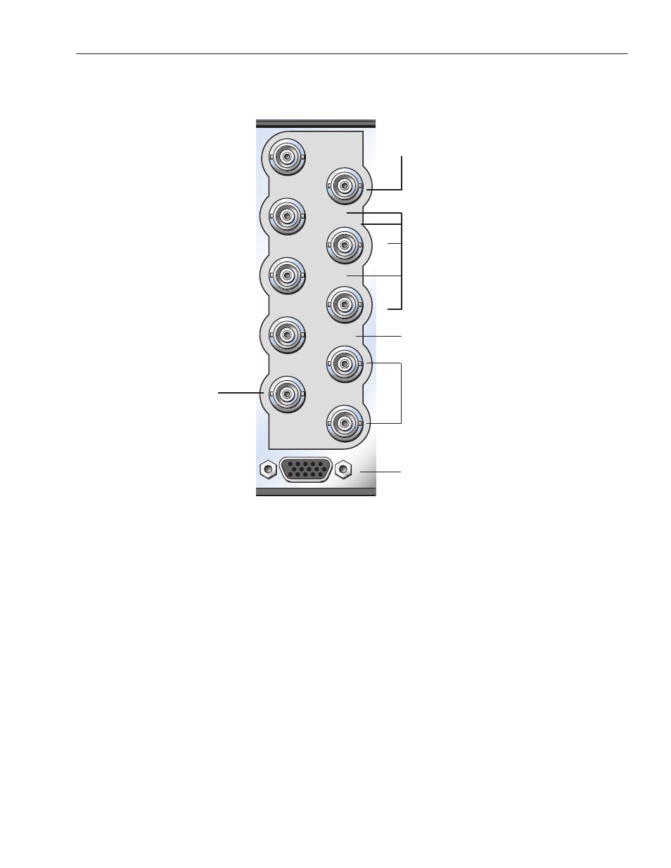
Model 7435 and 9455 Clean and Quiet Protection Switches
Out 5
Out 2
Primary In
Ref In
Sec Loop Out
Out 3
Out 4
Secondary In
Pri Loop Out
Fail-safe Out
9455 CS
Control
Connect the secondary (backup)
digital signal to the Secondary In
BNC and loop the Sec Loop Out
BNC to another destination in the
facility if needed.
Connect the Protect Out
BNCs to destinations.
Connect Fail-safe Out to the
final destination.
Connect the primary digital
signal to the Primary In BNC
and loop the Pri Loop Out
BNC to another destination in
the facility if necessary.
Connect the 23700048 Interface
Adapter Cable to provide a 9-pin
GPI connector for Control and an
Ethernet connection for software
upgrades. See photo and details on
the following page.
3RU Backplane
Connect NTSC or PAL analog
video, Tri-Level Sync or
10 MHz precision reference to the
Reference In BNC.
Backplane Diagram