Installation procedures – H3C Technologies H3C S12500 Series Switches User Manual
Page 33
23
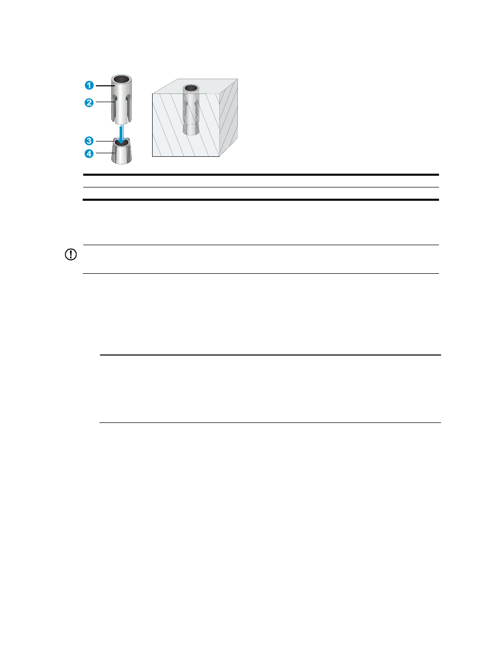
Figure 19 Installing the wall anchor
(1) Shank
(2) Groove
(3) Plug
(4) Spade-shaped wedge
Installation procedures
IMPORTANT:
Allow 0.8 m (2.62 ft) of clearance around the switch for heat dissipation.
To install the switch:
1.
Hold the two sides of the switch and steadily move the switch to the workbench.
2.
Lift the switch a little higher than the workbench and put it on the workbench.
3.
(Optional.) Install the cable management brackets on both sides of the switch and fasten the
screws, as shown in
NOTE:
The circled areas in
are the cable management bracket installation holes.
•
An S12504 switch has two columns of installation holes. You can choose either column for
installation.
•
An S12508 or S12518 switch has one column of installation holes.