Configuration procedure, Configuring mld snooping, Overview – H3C Technologies H3C S12500-X Series Switches User Manual
Page 151
141
•
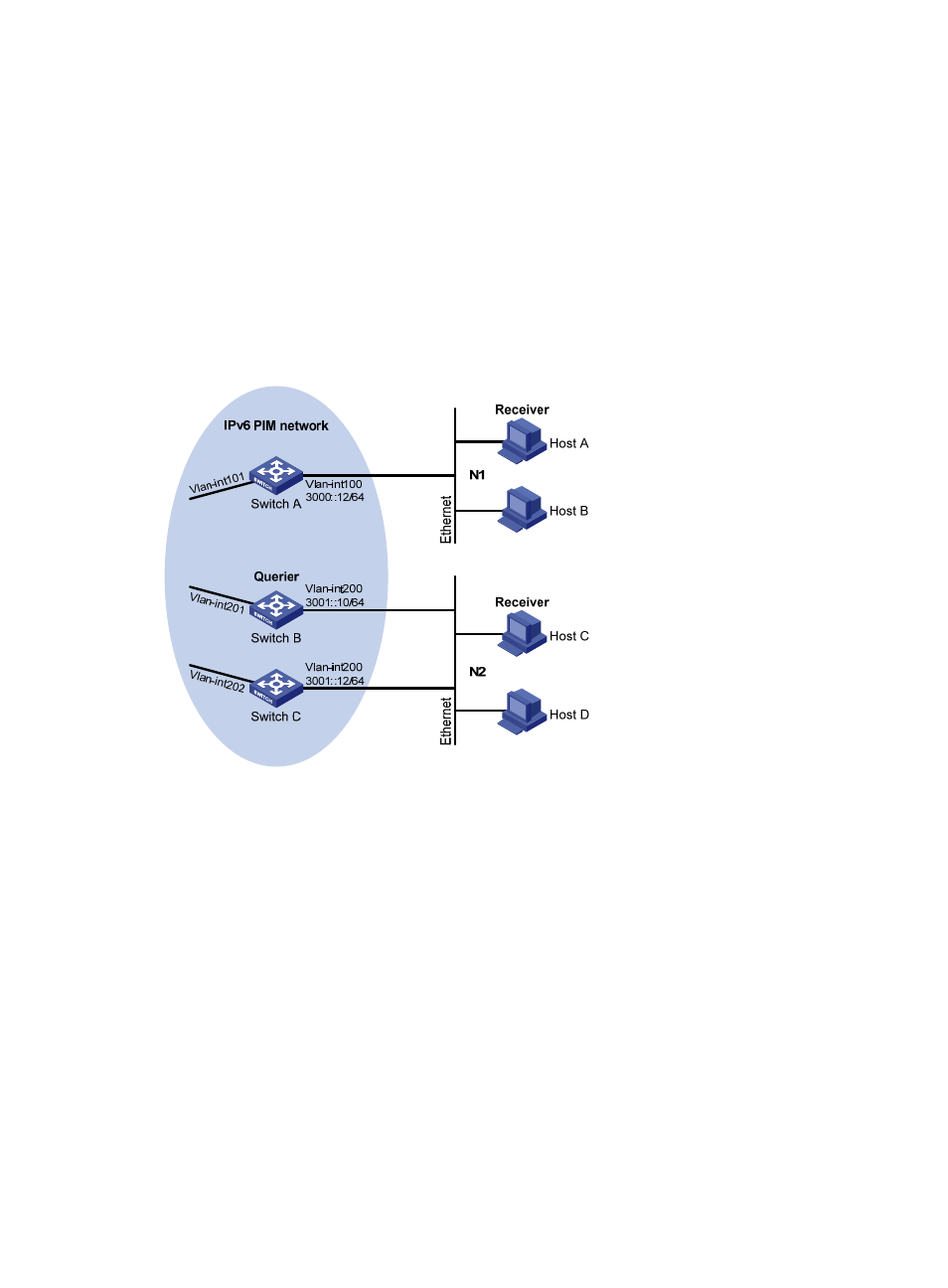
VOD streams are sent to receiver hosts in multicast. Receiver hosts of different organizations form
stub networks N1 and N2. Host A and Host C are multicast receiver hosts in N1 and N2,
respectively.
•
MLDv1 runs between Switch A and N1, and between the other two switches (Switch B and Switch
C) and N2.
•
Switch A acts as the MLD querier in N1. Switch B acts as the MLD querier in N2 because it has a
lower IPv6 address.
Configure the switches to achieve the following goals:
•
The hosts in N1 can join only the IPv6 multicast group FF1E::101.
•
The hosts in N2 can join any IPv6 multicast groups.
Figure 43 Network diagram
Configuration procedure
1.
Assign an IPv6 address and prefix length to each interface as shown in
. (Details not
shown.)
2.
Configure OSPFv3 between the switches to make sure the following conditions are met: (Details
not shown.)
{
The switches are interoperable at the network layer.
{
The switches can dynamically update their routing information.
3.
Enable the IPv6 multicast routing, MLD, and IPv6 PIM-DM:
# On Switch A, enable IPv6 multicast routing globally.
<SwitchA> system-view
[SwitchA] ipv6 multicast routing
[SwitchA-mrib6] quit
# Enable MLD on VLAN-interface 100 (the interface that connects to the stub network).
[SwitchA] interface vlan-interface 100
- H3C S9800 Series Switches H3C S5560 Series Switches H3C S5130 Series Switches H3C S5120 Series Switches H3C S12500 Series Switches H3C SR8800 H3C SR6600-X H3C SR6600 H3C WX6000 Series Access Controllers H3C WX5000 Series Access Controllers H3C WX3000 Series Unified Switches H3C LSWM1WCM10 Access Controller Module H3C LSWM1WCM20 Access Controller Module H3C LSQM1WCMB0 Access Controller Module H3C LSRM1WCM2A1 Access Controller Module H3C LSBM1WCM2A0 Access Controller Module