Mst region, Figure 13 basic concepts in mstp – H3C Technologies H3C WX3000E Series Wireless Switches User Manual
Page 60
51
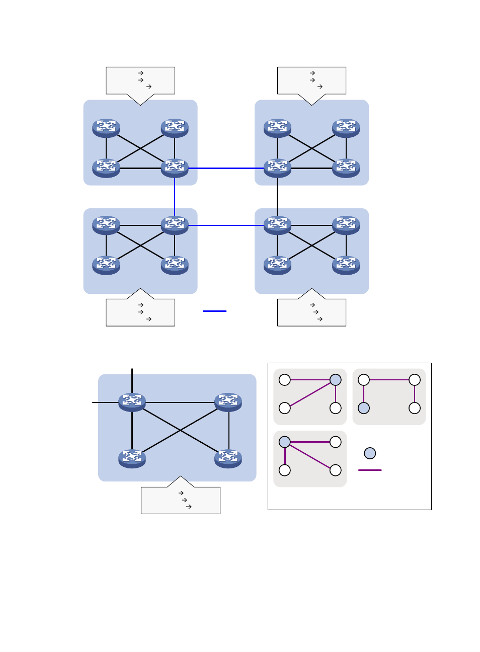
Figure 13 Basic concepts in MSTP
Figure 14 Network diagram and topology of MST region 3
MST region
A multiple spanning tree region (MST region) consists of multiple devices in a switched network and the
network segments among them. All these devices have the following characteristics:
•
A spanning tree protocol enabled
•
Same region name
MST region 1
MST region 2
MST region 3
MST region 4
VLAN 1
MSTI 1
VLAN 2
MSTI 2
Other VLANs
MSTI 0
VLAN 1
MSTI 1
VLAN 2
MSTI 2
Other VLANs
MSTI 0
VLAN 1
MSTI 1
VLAN 2
MSTI 2
Other VLANs
MSTI 0
VLAN 1
MSTI 1
VLAN 2&3
MSTI 2
Other VLANs
MSTI 0
CST
MST region 3
Device A
Device C
Device B
Device D
VLAN 1
MSTI 1
VLAN 2&3
MSTI 2
Other VLANs
MSTI 0
To MST region 4
To
M
S
T reg
io
n
2
B
A
C
D
MSTI 1
A
B
C
D
MSTI 0
B
D
MSTI 2
C
A
Regional root
MSTI
Topology of MSTIs in MST region 3