Control panel cabling – Grass Valley Kayenne K-Frame Installation Planning Guide Dec 03 2014 User Manual
Page 46
46
KAYENNE K-FRAME — Installation Planning Guide
Section 5 — Control Surface Cabling
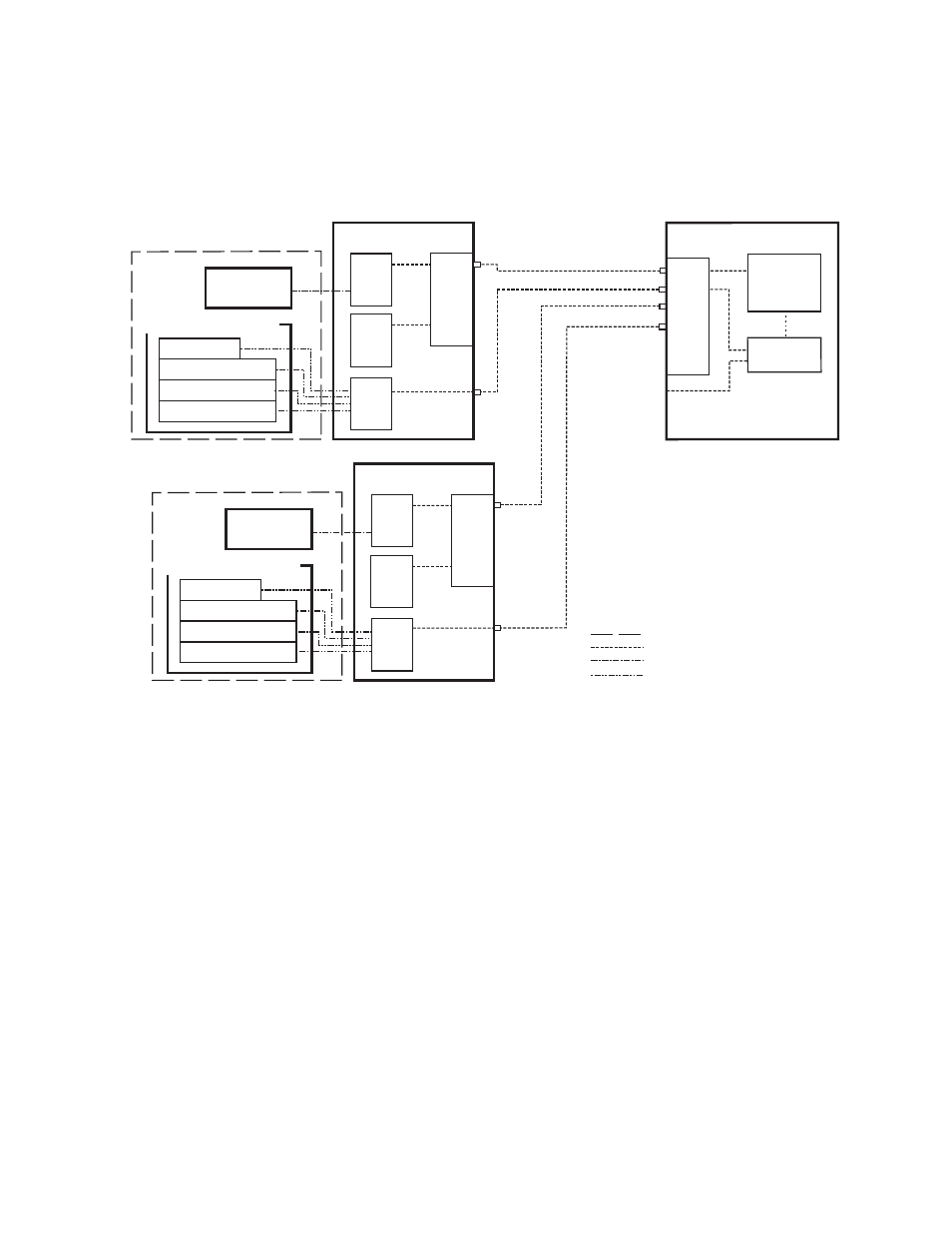
Using a second PCU, K-Frame suites can be located anywhere on the net-
work, permitting system control from different rooms, floors, or even dif-
ferent buildings (
).
Figure 4. Two Suites Using Two PCUs
Note
Refer to the K-Frame documentation set for important default IP address
information.
Control Panel Cabling
Connectors on the outside bottom of the Control Panel tray connect to
numbered ports on the PCU, using special multi-pin cables that carry both
power and communications signals. Special cables are also used to connect
the Menu Panels to the PCU.
CAUTION Do not connect or disconnect the multi-pin cables linking a Kayenne Control
Panel tray or Menu Panel to the PCU while the PCU is powered up. Damage
to the equipment can result.
8877_05
Menu Panel
Kayenne Control Panel
Local Aux Stripe
ME Stripe
ME Stripe
ME Stripe
Suite Boundary
Ethernet
Custom Multi-Pin (Menu, 15m / 50ft max length)
Custom Multi-Pin (Panel, 15m / 50ft max length)
Ethernet
(100m / 300ft max single hop length,
unlimited distance using switches)
Panel Main LAN
Eh
te
rne
t Swi
tch
1
2
3
4
5
6
7
8
Kayenne PCU 1
Menu
CPU
Panel
CPU
Menu Panel
Kayenne Control Panel
Local Aux Stripe
ME Stripe
ME Stripe
ME Stripe
Panel Main LAN
Eh
te
rne
t Swi
tch
1
2
3
4
5
6
7
8
Kayenne PCU 2
Menu
CPU
Panel
CPU
Menu
CPU
(option)
Menu
CPU
(option)
Internal Control
K-Frame Video Processor
Video
Processor
CPU
Image Store
Eh
te
rne
t Swi
tch
7
8
1
2
3
4
5
6
Kayenne Suite 1
Kayenne Suite 2