Installation, Making signal connections, Rtr expansion – Grass Valley NV8288 v.1.5 User Manual
Page 46: Diag (38.4 kbaud)
36
Rev 1.5 • 24 Sep 09
3. Installation
Making Signal Connections
puts. Connected routers must be situated physically next to each other, either top to bottom or side
to side.
The NV8288-Plus contains 48 expansion connections, located on the rear of the router. All 48
expansion connections must be connected to properly connect two frames together. Each signal
expansion connection corresponds to six output signals. For example, the expansion connection in
the upper, right corner corresponds to Outputs 1–6. (See Figure 2-6 on page 10.)
The signal expansion connections use a proprietary expansion cable provided by Miranda
(WC0089). The expansion connectors on the cable are colored-coded (one side black; one side sil-
ver) to ensure that they are installed correctly. The connector pins are fragile and can easily bend or
break if forced.
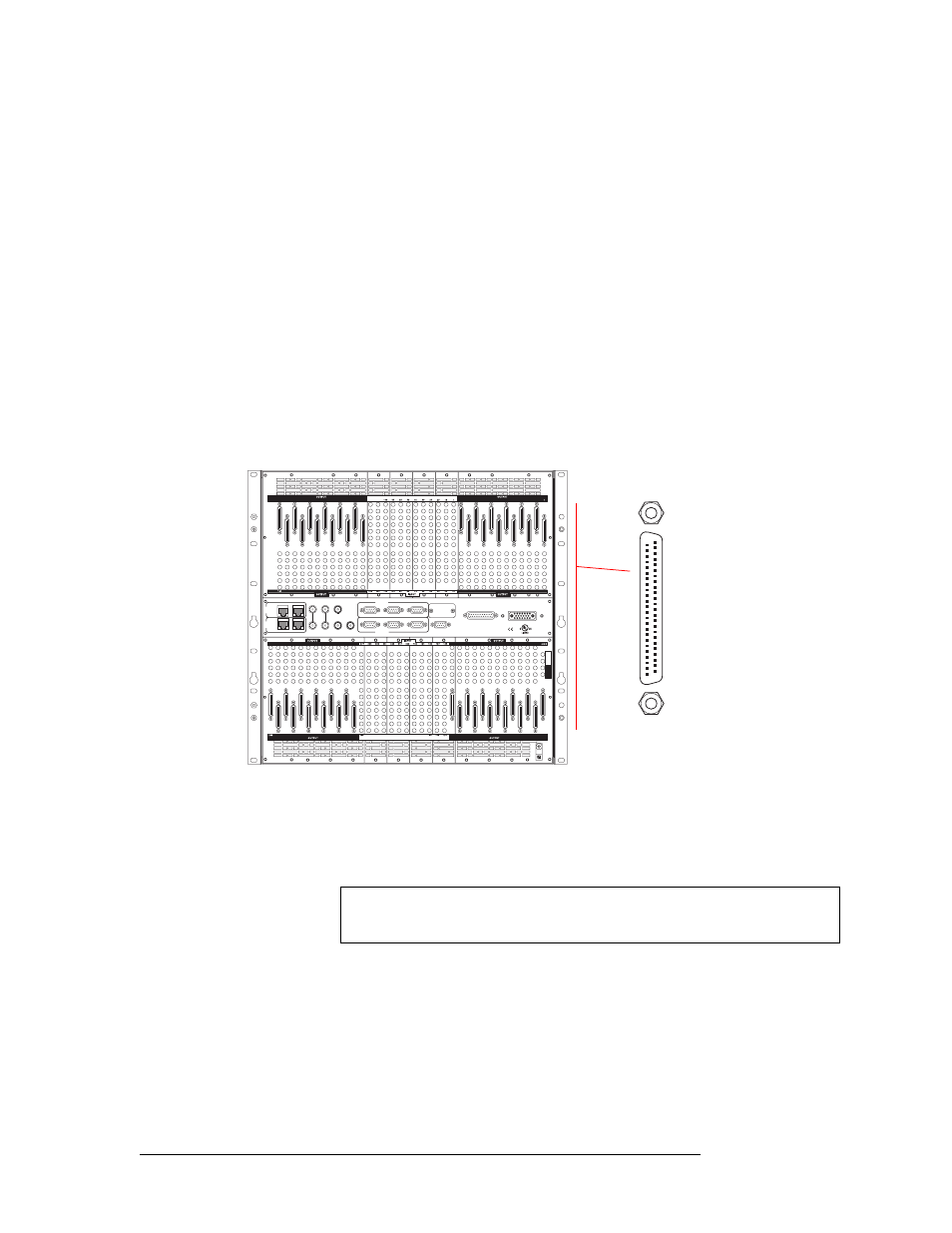
How to Make Signal Expansion Connections between Two Routers
1 Locate the signal expansion connections on the rear of the two router frames you are connect-
ing, as shown in Figure 3-10. The routers should be situated close together.
Figure 3-10. Expansion Connections for Connecting Two NV8288-Plus Routers
2 Facing the rear of the first router (router 1), locate the expansion connections in the upper half
of the frame.
Connect one end of the expansion connector cable (WC0089) to the expansion connection mak-
ing sure that the connector is positioned as follows. (See Figure 3-11.)
• Black side of connector faces right.
• Silver side of connector faces left.
RTR EXPANSION
E146905
10/100 BT
10/100 BT
RTR EXPANSION
VIDEO
REF 1
LOOP
VIDEO
REF 2
LOOP
AUX 1
AUX 2
CTRL 1
CTRL 1
CTRL 2
CTRL 2
ALARMS
POWER SUPPLY
MONITORS
POWER INPUT
TIME
CODE
PRI
CTRL
SEC
CTRL
PRI CTRL
SEC CTRL
DIAG (38.4 Kbaud)
DIAG (38.4 Kbaud)
79
85
91
97
103
109
115
121
127
133
139
73
7
13
19
25
31
37
43
49
55
61
67
120
126
132
8
3
1
108
114
84
90
96
102
8
7
36
42
48
54
60
66
72
12
18
24
30
6
223
229
235
241
247
253
259
265
271
277
283
217
175
169
151
157
163
145
181
187
193
199
205
211
156
162
168
174
180
186
192
198
204
210
216
150
228
234
240
246
252
258
264
222
270
276
282
IN
1
IN
2
OUT
1
OUT
2
Outputs 144–73
Outputs 72–1
Inputs 144–1
Outputs
288–217
Outputs
216–145
Inputs 288–145
Caution
The connector pins are fragile. Forcing the connector can cause damage. The
connectors are color-coded to ensure that they are attached correctly.