2 overall view – Grass Valley ASD-771p User Manual
Page 10
Advertising
ASD-771p/75/110 - Guide to Installation and Operation
3
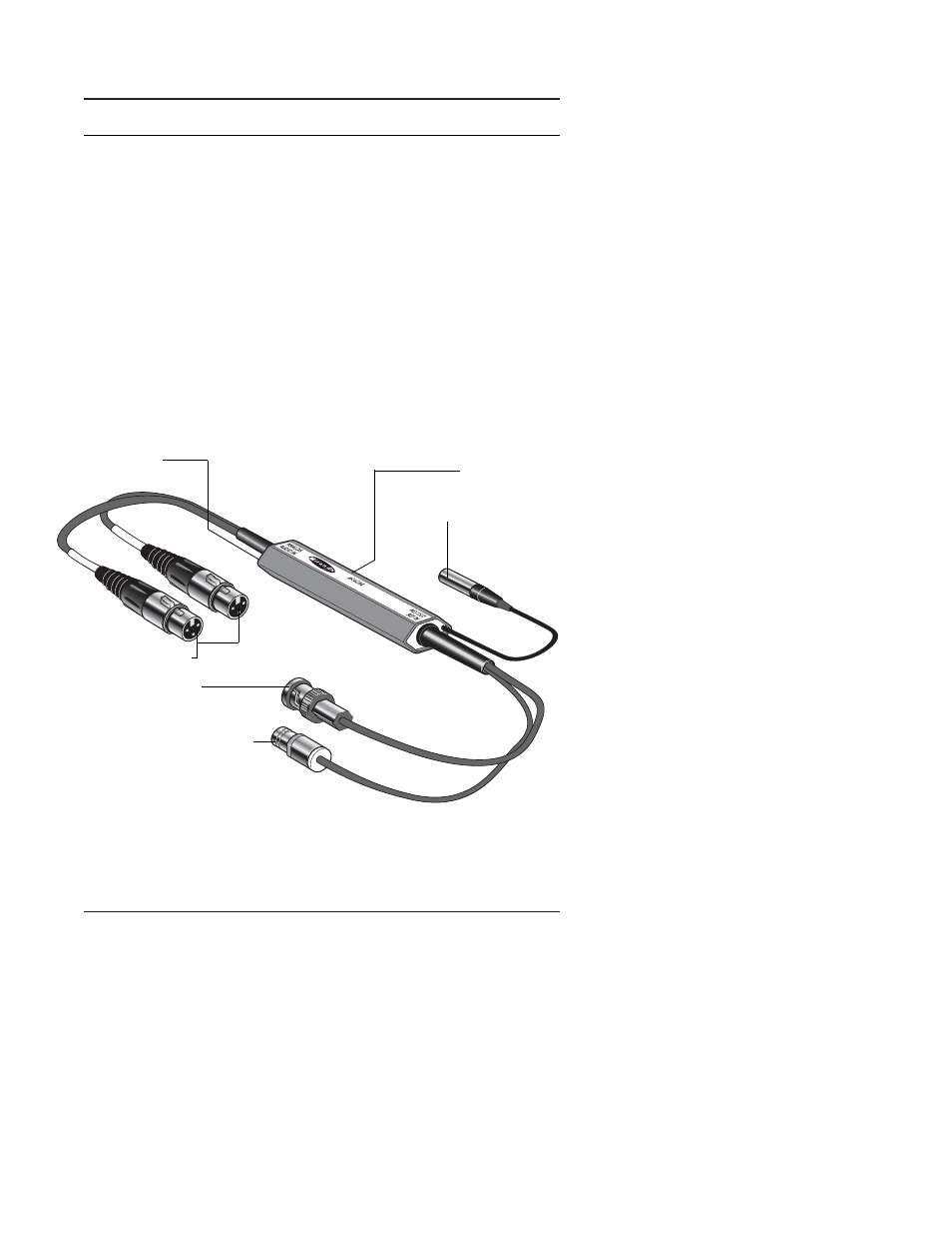
2 Overall view
The figures below represents the ASD-771p/75 and the ASD-
771p/110. The analog stereo audio source is connected to the
two XLR3 input connectors.
A multicolor LED provides module statuses. A mini slide switch
“Test” configures the test mode. The input level is configurable
using two 3-positions slide switches “Left” and “Right”.
Output is provided by a BNC socket over 75
Ω and a three-point
XLR connector over 110
Ω.
Power supply is connected to a mini-XLR type connector.
Figure 2.1 ASD-771p, 75
Ω Version
LEFT
RIGHT
Status LED
Input connectors
Slide switches
DC power input connector
Output connector
Reference input connector
Advertising