4 operation – Grass Valley ASD-771p User Manual
Page 14
Advertising
ASD-771p/75/110 - Guide to Installation and Operation
7
4 Operation
4.1 Switch Settings
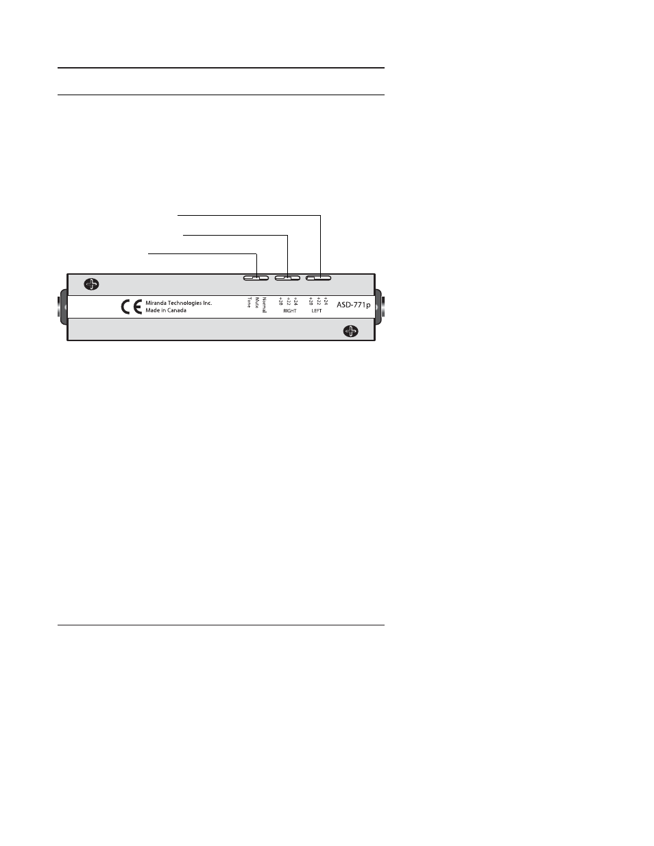
Figure 4.1 indicates the locations of the miniature switches at the
back of the ASD-771p.
Figure 4.1 ASD-771p
Switches location
a- Input Level Switches
The adjustment of the stereo analog input level is configurable
with a potentiometer (±1 dB) located on the PCB and with two 3-
positions slide switches “LEFT” and “RIGHT”. Three levels of
attenuation of the full scale output (0 dBFS) are provided: +20,
+22 or +24 dBU.
b- Test Switch
Two test functions are offered:
Tone
EBU tone generator: sine wave 1 kHz at -18 dBFS inter-
rupted on left channel (250 ms/3 s)
Left Input level adjustment
Right Input level adjustment
Test Mode selection
Advertising