Figure 2. removing the circuit board hold-downs – Grass Valley PLSDST3 User Manual
Page 11
Advertising
Preparing the Profile Video File Server
DST 312/412 Interface Kit Installation
5
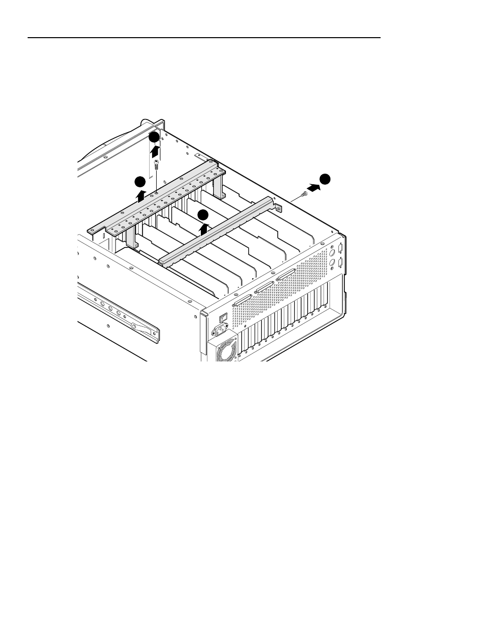
3. Remove the two circuit board hold-downs as shown in Figure 2. Both
hold-downs are held in place by T-10 TORX head screws, and must be
removed in order to remove or install any of the circuit boards.
Figure 2. Removing the circuit board hold-downs
9675-2
1
3
4
2
Advertising
This manual is related to the following products: