Figure 5 – Grass Valley Trinix Back-Up Power Supplies Jan 13 2012 User Manual
Page 48
48
Trinix — Installation and Service Manual
Section 3 — Installation for Legacy Frames
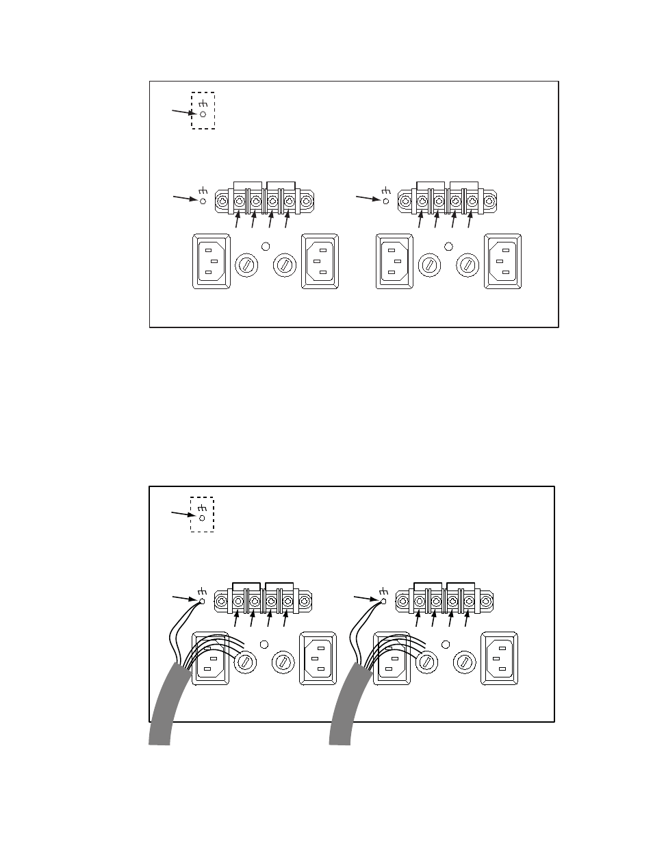
Figure 5. DV-33512 Power Supply Connectors Showing Reference Numbers Used in this Document
c.
Remove the “DC IN +” and “DC IN -” screws (3), (4), (5), (6), (8), (9),
(10), and (11).
d.
Locate the two DC power ground studs (2) and (7). Use a nut driver
to remove one nut (only) and one washer (only) from each stud.
e.
Connect the supplied jumper wires and external power supply
cables as shown in
.
Figure 6. Jumper and External Power Supply Wiring (Partially Complete)
DC IN -
DC IN +
PS B
PS A
DC IN -
DC IN +
PS D
PS C
(1)
(2)
(7)
(3)
(4)
(5)
(6)
(8)
(9)
(10) (11)
DC IN -
DC IN +
PS B
PS A
DC IN -
DC IN +
PS D
PS C
(1)
(2)
(7)
(3)
(4)
(5)
(6)
(8)
(9)
(10) (11)
to external A/B power supply(s)
to external C/D power supply(s)