2 removal, 3 closure and verification – SMA FLX Series GSM Option Kit User Manual
Page 6
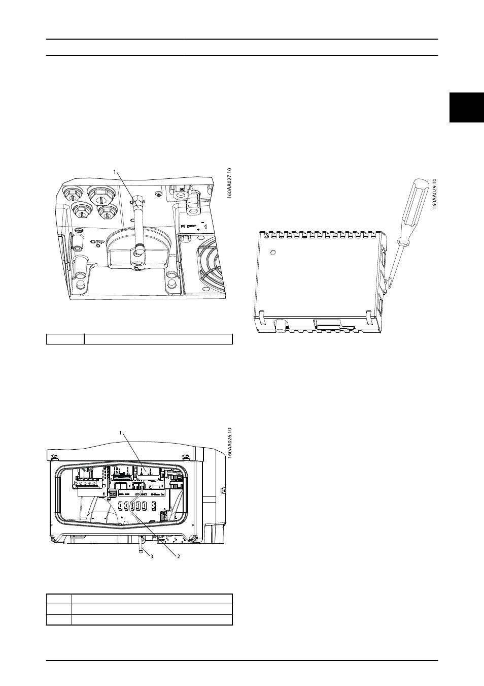
of the inverter base plate and is labelled ‘GSM’.
See Illustration 1.2.
5.
Take the antenna cable. Insert the bulkhead
connector on the antenna cable through the
antenna mounting hole. Fasten it with washer
and nut on the outside of the base plate.
6.
Mount the antenna on the bulkhead connector.
See Illustration 1.4.
Illustration 1.4 Correctly-mounted Antenna
1
Antenna
7.
Take the free end of the antenna cable.
-
Fasten the connector to the GSM option
at the point labelled ‘GSM Ant.’ See (1)
in Illustration 1.5.
-
Check the finished installation is correct,
according to Illustration 1.5.
Illustration 1.5 Correctly Mounted GSM Option with Antenna
1
GSM option
2
Antenna cable
3
Antenna
1.2 Removal
To remove the option:
1.
Insert a screwdriver at the snap connector on the
side of the option.
2.
Apply pressure sideways to release the snap
connector as shown in Illustration 1.6.
3.
Lift the option off the option slot.
Illustration 1.6 Removal of Option
1.3 Closure
and
Verification
1.
Close the cover of the inverter installation area.
Ensure that the cover is correctly fastened.
2.
Turn on PV and AC connection.
3.
Verify that the option is detected. Refer to
2.1.1 Verification.
Installation
L00410627-03_2q / Rev. date: 2014-06-20
5
1
1