Yaskawa G5 High Slip Braking User Manual
Page 2
Date: 07/01/04, Rev: 04-07
Page 2 of 3
TM.G5SW.009
Overview:
The High Slip Braking (HSB) function dissipates regenerative deceleration energy in the motor by
creating a large slip condition. The function is ideal for high inertia rotating loads such as centrifuges,
presses, and blowers, and requires no braking resistor. Braking time can be achieved that is
approximately 50% of the time required to decelerate a load normally without using a braking resistor.
The HSB function can be used for motors operating in the constant power range.
•
HSB only functions for motor stopping, not a change in frequency reference.
•
Like the Fast Stop function, the inverter cannot be restarted during a HSB stop.
•
Normal deceleration and HSB can be used together. The HSB function is initiated automatically upon
stopping when the inverter is operated between two programmed frequencies.
•
For HSB to work effectively, the motor should be 160kW or less. The load should have fairly high
inertia, with normal deceleration (no braking resistor) requiring 30 - 180 sec.
•
The HSB braking duty cycle should be 5% or less and the stopping time should limited to 90 sec or
less, as the regenerative energy is dissipated as heat in the motor. When the motor becomes
overloaded it will fault on OL1 (normal motor overload) or OL7 (HSB overload).
•
HSB can only be used in the V/f control modes (open loop or with PG).
•
To maximize the performance of HSB, verify parameter E2-05 (Motor Terminal Resistance) is set
properly. If this data is not known, execute the auto-tuning function in either Open Loop Vector or Flux
Vector control mode and then change the control mode to either of the V/f modes for using HSB.
•
HSB cannot be used with synchronous motors.
•
It is not possible to use HSB together with the KEB (Kinetic Energy Braking) function.
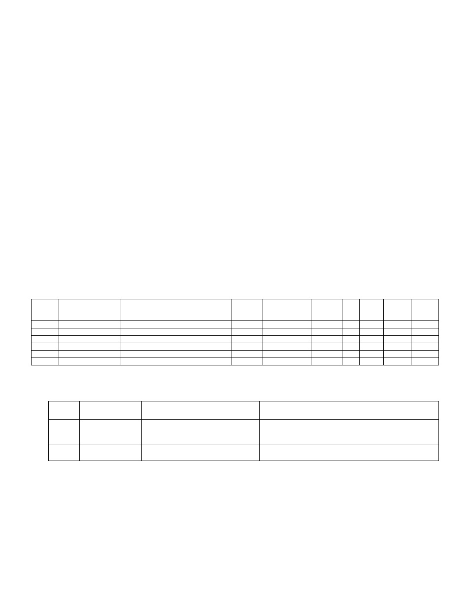
Additional Parameters:
No.
Digital Operator
Display
Parameter Description
Unit
Setting Range
Default
V/f
V/f w/
PG
Open
Loop
Vector
Flux
Vector
C9-01
HSB Down Freq
HSB Decel Frequency Width
1%
1 ~ 20
7
A
A
-
-
C9-02
HSB Current
HSB Current Limit
1%
100 ~ 200
150
A
A
-
-
C9-03
HSB Dwell Time
HSB Stop Dwell Time
0.1sec
0.1 ~ 10.0
1.0
A
A
-
-
C9-04
HSB OL Time
HSB OL Time
1sec
20 ~ 1200
40
A
A
-
-
C9-13
HSB On Freq
HSB On Frequency
0.01Hz
0.00 ~ 400.00
0.00
A
A
-
-
C9-14
HSB Off Freq
HSB Off Frequency
0.01Hz
0.00 ~ 400.00
0.00
A
A
-
-
Additional Faults:
Fault
Code
Digital Operator
Display
Fault Description
Cause
OL7 HSB-OL
HSB
Overload
The inverter output frequency during HSB did not change
within the time set in C9-04 (excessive machine inertia
present).
OPE13
HSB Select Err
HSB Parameter Setting Error
C9-13 > C9-14 or
C9-14 > 0 but control mode is not V/f
Description of Functionality:
When the inverter is running between the output frequencies set in C9-13 (HSB On Frequency) and C9-
14 (HSB Off Frequency) and the run command is removed, the inverter will stop by HSB. The inverter
cannot be restarted during an HSB stop.
Parameter C9-01 (HSB Decel Frequency Width) sets how aggressively the inverter decreases the output
frequency as it stops the motor. If overvoltage (OV) faults occur during HSB, parameter C9-01 may need