Motion control, 6 typical control wiring diagram, Speed (+) time typical homing profile – Yaskawa G5 Motion Control User Manual
Page 5
Motion Control
Date: 08/18/04, Rev: 04-08
Page 5 of 22
TM.G5SW.020
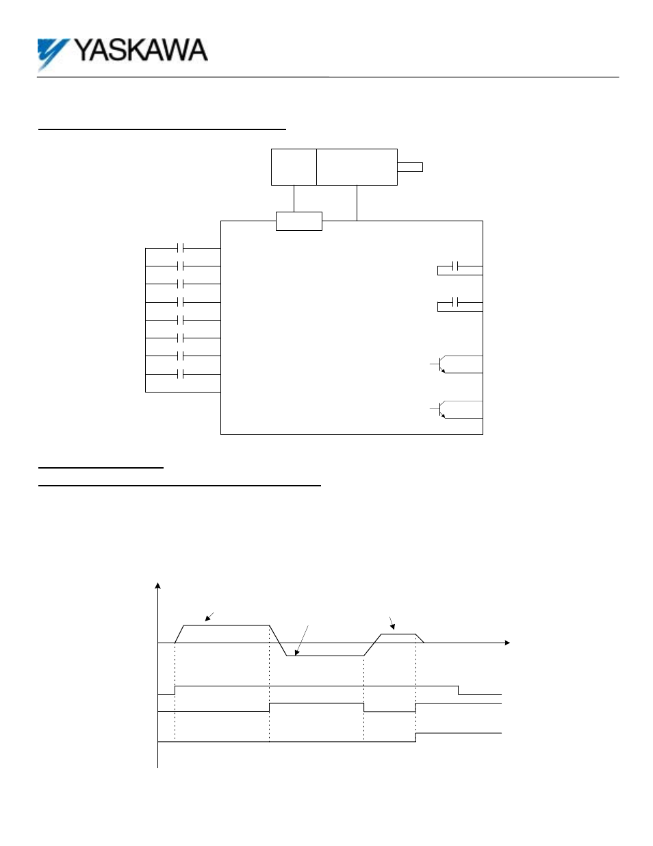
1.6 Typical Control Wiring Diagram
GPD515/G5
Controller
Encoder
PG-X2
1
Move Positive
INPUTS
O UTPUTS
2
7
3
Enable
4
Hom e switch
5
Hom e com m and
6
10
9
Move
Com plete
20
19
Drive
Fault
25
27
Move in
progress
Move Negative
Motor
T1-T2-T3
8
Drive Com m on
11
Multi-step ref #1
Multi-step ref #2
Multi-step ref #3
26
27
Hom e
Status
2.0 Timing Charts
2.1 Typical Homing Profile Timing Chart
Homing begins with movement in the direction (home accelerations and velocities) specified while looking for the home
limit switch. Once the home limit is found the specified edge of the limit is then sought out. (The home limit switch
polarity is also settable). Once the proper edge is found the home backup function can be used to reverse the motor and
re-approach the limit edge at the home final velocity (a separate value from the home velocity) until the edge is found
again.
(-) Speed (+)
Time
Typical Homing Profile
Homing Speed
Home command
Home Switch
Home Status
Home Final
Speed
Home BU
Speed