Yaskawa AO-001 User Manual
Isolated analog output option card ao-001
Yaskawa Electric America, Inc. – www.drives.com
IG.AFD.52, Page 1 of 5
Date: 11/03/04, Rev: 04-11
Isolated Analog Output Option Card
AO-001
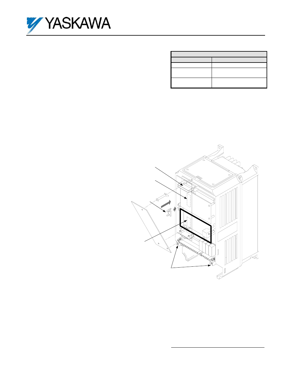
Figure 2. AO-001 Option Card Installation
Grounding Terminal
4CN
Option Card A
2CN
Option Card C
3CN
Option Card D
Option Clip
Part Number: AO-001 (UTC000053)
Applicability: F7, G7, GPD515/G5. Note: The AO-001 (UTC000053)
replaces the AO-12B2 (UTC000016), which was exclusive to the
GPD515/G5 and not compatible with the F7 or G7.
Introduction: The Isolated Analog output option board (Figure 1) is
mounted on the drive’s control board and enables the user to employ
precision, isolated analog signals to monitor drive outputs (U1-XX) as
indicated in tables 5 and 6.
Receiving: All equipment is tested against defect at the factory. Report any damages or shortages evident when the
equipment is received to the commercial carrier who transported the equipment.
Warning: Hazardous voltage can cause severe injury or death. Lock all power sources feeding the drive in the “OFF”
position.
Caution: This option card uses CMOS IC chips. Use proper electrostatic discharge (ESD) protective procedures when
handling the card to prevent I.C. damage or erratic drive operation.
Important:
1. If this option is being installed in a drive
with an encoder feedback option card, that
card will need to be temporarily removed to
allow access to connector 3CN on the
drive’s control board and TB1 of the AO-
001 option card.
2. Before installing this option, a technically
qualified individual, who is familiar with this
type of equipment and the hazards
involved, should read this entire installation
guide.
Installation and Wiring:
1. Disconnect all electrical power to the drive.
2. Remove the drive’s front cover.
3. Check that the “CHARGE” indicator lamp
inside the drive is off.
4. Use a voltmeter to verify that the voltage at
the incoming power terminals (L1, L2, L3)
has been disconnected.
5. Option Card Installation: See Figure 2.
a) Position the option card above 3CN on
the control board and gently press the
card into place.
6. Wiring. Refer to Figure 3 and Table 2.
Make wire connections between the AO-
001 card and the drive’s control circuit, as
well as external monitoring circuits.
Observe the following:
a) Keep the AO-001 (i.e. control circuit)
wiring separate from main circuit
input/output wiring.
A separate metallic grounded conduit with only the option card’s wiring running through it is preferred.
b) To prevent erroneous operation caused by noise interference, use shielded cable for control signal wiring, and
limit the distance to 50m (165 feet) or less.
c) Connect the option card ground wire (CBL1) to the drive’s ground terminal TB3 (12 for G5).
7. Adjustment: The type of output the AO-001 option card will produce is selected with several jumpers and
parameters. Refer to Tables 3 and 4 and Figure 3 to select the appropriate output type and scaling. Note:
The variable resistors VR1 thru VR4 are factory set and require no further adjustment.
8. Reinstall and secure the drive’s front cover.
9. Place this instruction sheet with the drive’s technical manual.
Table 1. Specifications
Parameter
Value
Output Resolution
11 bit + sign (1/2048)
Output Current
4 to 20mA (Isolated)
0 to 20mA (Isolated)
Output Voltage
-10VDC to +10VDC
(Isolated)