Analog input option card ai-14b – Yaskawa AI-14B User Manual
Page 3
Yaskawa Electric America, Inc. – www.drives.com
IG.AFD.54, Page 3 of 4
Date: 07/01/04, Rev: 04-07
Analog Input Option Card
AI-14B
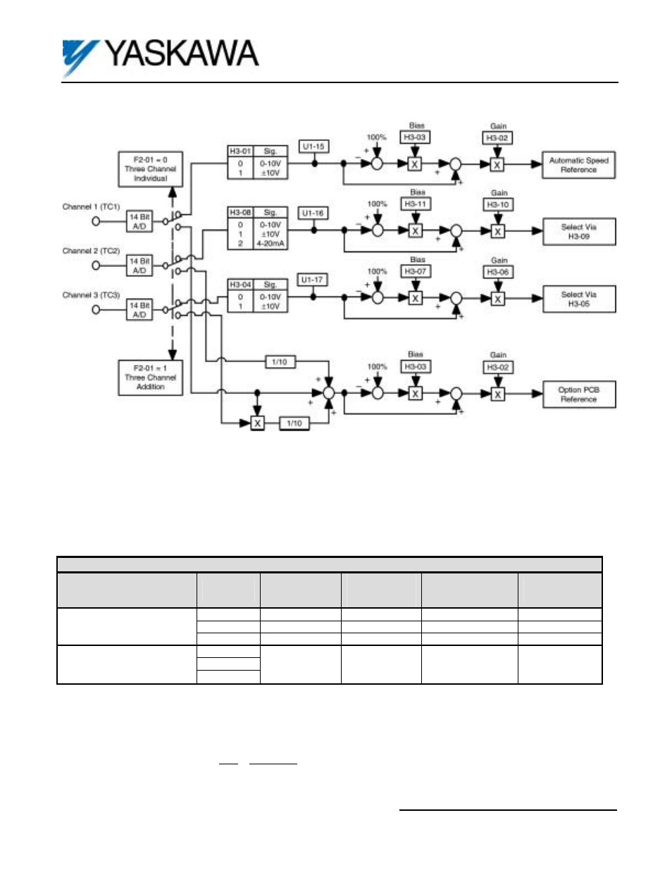
Figure 4. AI-14B Block Diagram
Figure 4 shows two possible modes of operation for the AI-14B option card when installed in the drive. These modes are
selected by drive parameter F2-01 (AI-14B Input Selection). When F2-01 is set to “ 0 “, 3-channel individual mode is selected.
In this mode the AI-14B option replaces the analog inputs on the drive’s main control board. See Table 3.
When F2-01 is set to “ 1 “, 3-channel addition mode is selected. In this mode, the AI-14B option combines the three channels
together as shown above. This composite signal becomes the primary speed reference when the reference source parameter
is set to “Option PCB” (b1-01 = 3).
Table 3. Adjustment of the Input Signals
(4)
Mode
AI-14B
Terminal
F7/G7
Control Board
Terminal
GPD 515/G5
Control Board
Terminal
Gain
Parameter
(3)
Bias
Parameter
(3)
TC1 A1
13
H3-02 H3-03
TC2 A2
14
H3-10 H3-11
3-Channel Individual
(1)
TC3 A3
16
H3-06 H3-07
TC1
TC2
3-Channel Addition
(2)
TC3
Speed
Reference
when b1-01=3
Speed
Reference
when b1-01=3
H3-02 H3-03
(1) When using the 3-Channel Individual Mode,
Channel 1 (TC1) becomes the primary speed reference.
Channel 2 (TC2) function can be configured using parameter H3-09.
Channel 3 (TC3) function can be configured using parameter H3-05.
(2)
To use the 3-Channel Addition Mode, parameter b1-01 (Reference Source) must be set to “ 3 “ (Option PCB)
Frequency Reference = TC1 + TC2 + TC3 x TC1
10 10
(3)
See Figure 5.
(4)
Warning: If the application requires that reverse motor rotation be prohibited, parameter b1-04 must be set to “1” so
the motor will stop whenever the polarity of the input signal becomes negative.