Control connections, Ig.v7.69 – Yaskawa GPD315 User Manual
Page 5
IG.V7.69
- 5 -
Date: 07/01/04, Rev: 04-07
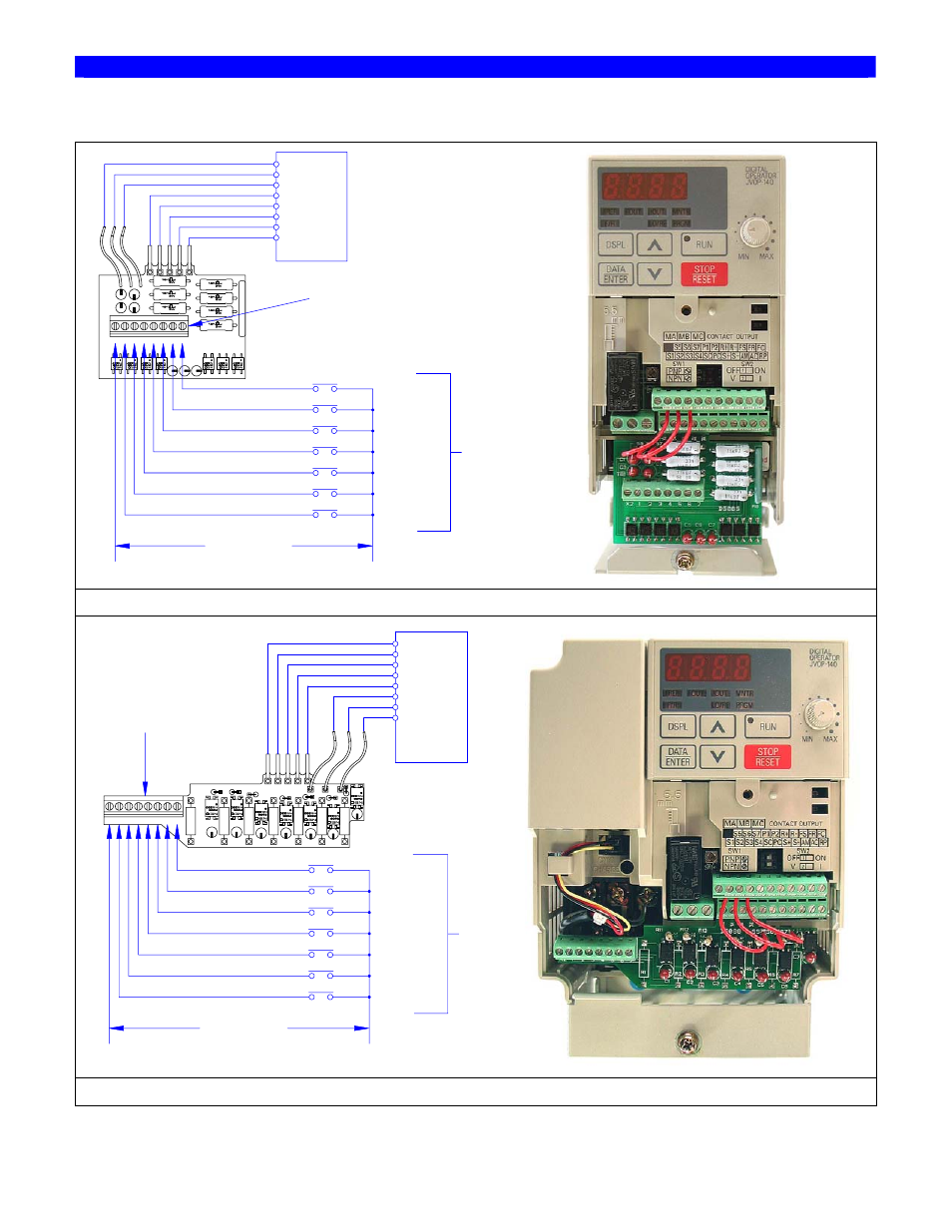
Control Connections
1
X2
5
4
3
2
7
6
C1
C2
C4
C3
C5
C6
C7
TB1
R8
DS085
S5 S6 S7
F
a
c
to
ry
D
e
fa
u
lt
S
e
tt
in
g
s
f
o
r
2
W
ir
e
C
o
n
tr
o
l
Speed Ref 1
Run / Stop
Forward
(S1)
External
Fault
Run / Stop
Reverse
Reset
Fault
(S3)
(S2)
(S4)
Speed Ref 2
Multi-Step
Multi-Step
Jog
Reference
(S5)
(S6)
(S7)
*
Indicates Componets Not Supplied
120VAC Control Voltage
*
Neutral
*
*
Line
*
*
*
*
*
S6
V7 Drive
S7
S3
S5
SC
S4
S2
S1
(SC)
Terminal TB1
Kit No. DI-004 (Board No. DS085)
X2 1
2
3
4
5
6
7
R1
R7
R6
R5
R4
R3
R2
C7
R11
R12
R13
DS088
C1
C2
C3
C4
C5
C6
S5
S6
S7
S1
S2
S3
S4
SC
S5
S6
S7
V7 Drive
*
Forward
Run / Stop
*
Reverse
Run / Stop
*
External
Fault
*
Fault
Reset
*
Multi-Step
Speed Ref 1
*
Multi-Step
Speed Ref 2
*
Jog
Reference
120VAC Control Voltage
Neutral
Line
*
Indicates Componets Not Supplied
*
F
a
c
to
ry
D
e
fa
u
lt
S
e
tt
in
g
s
f
o
r
2
W
ir
e
C
o
n
tr
o
l
(S7)
(S6)
(S5)
(S4)
(S3)
(S2)
(S1)
(SC)
Terminal TB1
Kit No. DI-005 (Board No. DS088)
Figure 1. Connection of Interface Card and Sample Control Schematic