P1000 ac drive quick start procedure, Page 2 of 2, Check motor direction (motor uncoupled from load) – Yaskawa P1000 AC Drive User Manual
Page 2: Changing parameters and monitoring the p1000, Application setup, Frequently asked questions
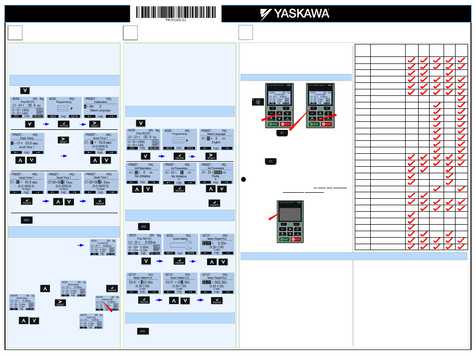
Check Motor Direction
(Motor uncoupled from Load)
Motor Rotation Test
In this step the motor is checked for proper direction and operation.
This test is to be performed solely from the digital operator. Apply
power to the P1000 after all the electrical connections have been
made and protective covers have been re-attached. At this point,
DO NOT RUN THE MOTOR, the Digital Operator should display as
shown in
Fig. 3
.
Fig. 3
Use precaution, and
refer to
Fig.1 or 2,
swap
any
two
of the
three
output leads to the motor
(U/T1, V/T2 and W/T3).
After the wiring change,
repeat
Step 7
and
recheck motor direction.
After the power has been turned OFF, wait at least five minutes
until the charge indicator extinguishes completely before touching
any wiring, circuit boards or components.
DANGER
If motor rotation is not correct, power down the drive, wait five
minutes and swap 2 motor leads at the drive output terminals.
!
Next, press and
hold
on the Digital Operator.
The motor should now be operating at low speed (6.00 Hz)
running in the correct forward (clockwise) direction.
Next, release on the Digital Operator.
Digital Operator
turned off.
Press
Green LED turns
on.
Green RUN
LED turns on.
FREQUENTLY ASKED QUESTIONS
Question: How do I reset the drive back to factory default settings?
Answer: Go to parameter A1-03 and set value 2
2220 for 2 wire control or 3
3330
for 3 wire control (Please refer to Step 3 for wiring diagram) or see
step 6: Application setup.
Question: How can I change the speed reference or start / stop control source?
Answer: Set parameter b1-01 for speed reference or b1-02 for start/stop
selection.
Question: How can I make the motor coast when a stop command is
activated?
Answer: Set parameter b1-03 Stopping Method to “1” Coast to Stop
Question: How do I adjust the time it takes the motor to speed up or slow
down?
Answer: Adjust the acceleration time parameter C1-01 and deceleration time
C1-02.
Question:
How do I set the maximum or minimum frequency?
Answer:
Set d2-01 = maximum upper frequency and d2-02 = minimum
frequency. E
Example: d2-01 set for 90% = 54 Hz maximum
frequency
(0.9 x 60Hz)
Question: How do I prevent my drive from tripping on an O
OV fault
(overvoltage) while my motor is ramping down?
Answer: Increase deceleration time parameter C1-02.
Question: How do I prevent my drive from tripping on an O
OL1 fault
(overload) while my motor is ramping down?
Answer: Verify motor rated current parameter E2-01 and motor overload
parameter settings L1-01 Motor overload selection, L1-02 Motor
overload protection time.
Question: I want to run my motor above the nominal motor speed?
Answer: Increase the value of parameter E1-04 Maximum Frequency
W
WARNING! Verify that the motor and system allow for this.
Step
5
Changing Parameters and
Monitoring the P1000
Step
6
Application Setup
Step
7
Page 2 of 2
This step shows how to access and modify a P1000 parameter as
well as how to monitor P1000 signals such as output frequency
and motor current.
Make sure all protective covers have been re-attached and power
is turned on. D
DO NOT RUN THE MOTOR.
Press two times until the digital operator shows the parameter menu.
Select Digit
Access Parameter Menu and Change Parameter Value
Monitor Motor Frequency and Motor Current
To monitor output frequency and motor current or other signals
individually, press once, then press
. Next press to select monitor
Use to select monitor signal.
Please refer to the P1000 Quick Start Manual, (Document No.
TOEP YAIP1U 01
) on how to access other drive monitors.
U1-02 Output Frequency
2X
2X
Inc./Dec. Selection
Inc./Dec. Selection
Go to Next Digit
Switch to Edit Mode
Save New Value
Modify Value
P1000 Digital Operator power-up state
Output Frequency and Motor Current can be monitored
simultaneously.
Digits
Flashing
Hold button for 3 sec. to go back to the main menu.
This step shows how to configure the P1000 for dedicated fan or
pump applications.
Make sure all protective covers have been re-attached and power is
turned on. D
DO NOT RUN THE MOTOR.
Available P1000 Application Macro’s:
·
Pump without Automatic Regulation
·
Pump with PI Control (Automatic pressure/flow regulation with transducer)
·
Fan without Automatic Regulation
·
Fan with PI Control (Automatic pressure/flow regulation with transducer)
Press two times until the digital operator shows the parameter menu.
Select Digit
Select Application
2X
Inc./Dec. Selection
Select Application
Switch to Edit Mode
Press to Select
Hold button for 3 sec. to go back to the main menu.
2X
Enter Application Parameters
3X
Select Parameter
Switch to Edit Mode
Save New Value
Modify Value
Hold button for 3 sec. to go back to the main menu.
Go Back to Main Menu
Application Parameters /
Frequently Asked Questions
Parameter
A1-03
Description
Initialization Mode =
General
2222
Pump
8008
Pump+PI
8009
Fan
8010
Fan+PI
8011
A1-06
Application Preset
Selection
E2-01
Motor Rated Current
b1-01
Frequency Reference
Selection
b1-02
Run Command
Selection
b1-03 Stopping
Method
b1-04
Reverse Operation
Selection
b5-12
PI Feedback Loss
Detection Selection
b5-19 PID
Setpoint
Value
b5-38
PID Setpoint User
Display
b5-39
PID Setpoint Display
Digits
b5-46 PID
Unit
Selection
b5-90 EZ
Sleep
Unit
b5-91 EZ
Minimum
Speed
b5-92 EZ
Sleep
Level
b5-94 EZ
Wake-up
Level
C1-01
Acceleration Time 1
C1-02
Deceleration Time 1
d1-01
Frequency Reference 1
d2-01
Frequency Reference
Upper Limit
d2-02
Frequency Reference
Lower Limit
H3-09
Terminal A2 Signal
Level Selection
L2-01
Momentary Power Loss
operation Selection
L5-01
Number of Auto Restart
Attempts
L5-04
Fault reset interval Time
L6-01
Torque Detection 1
Selection
L6-02
Torque Detection 1 Level
L6-03
Torque Detection 1 Time
o1-06
User Monitor Selection
Mode
o1-07
Second line Monitor
Selection
o1-08
Third line Monitor
Selection
Yaskawa America, Inc., 2121 Norman Drive South, Waukegan, IL 60085, (800) YASKAWA (927-5292) Fax (847) 887-7310, [email protected], www.yaskawa.com, Document Number: TM.P1000.01 03/25/2013 © Yaskawa America, Inc.
P1000 AC Drive
Quick Start Procedure