Jordan Valve Mark ED & ET Series Globe Style Control Valve (1-6) User Manual
Page 4
-4-
Packing Maintenance
TFE V-Ring Packing
Except where indicated, refer to Figure 7 for part de-
scriptions used in the following procedure.
1.
For spring loaded single TFE V-ring packing,
the spring (key 8) maintains the sealing
force on the packing. If leakage is detected
around the packing follower (key 13), tighten
the packing flange nuts (key 5) until the leak-
age stops. If the shoulder of the packing box is
touching the bonnet and leakage cannot be
controlled in this manner, see “Packing Re
placement”.
Packing Replacement
1.
Once the actuator and bonnet have been
separated from the body (refer to Steps 1-2 of
Disassembly procedure), remove the following
from the bonnet:
a.
Packing flange nuts (key 5)
b.
Packing flange (key 3)
c.
Felt wiper (key 12)
d.
Packing follower (key 13)
2.
Clean the packing box bore, spring (key 8),
washer (key 10), and the packing box ring (key
11).
3.
Install the valve plug assembly and mount the
bonnet to the body using new gaskets.
Use the sequence shown in Figure 4 to install
new packing and associated parts. Be
sure not to damage the packing during
installation. Replace the packing
flange (key 3), tighten the
packing flange nuts (key 5) until the shoul-
der of the packing follower (key 13) is ap-
proximately 5/8” from the top of the bonnet. If
leakage is detected around the packing fol-
lower, tighten the packing flange nuts until the
leakage stops.
4.
For graphite packing, tighten the packing
flange nuts to the maximum torque value in
Table 3. Then back off the nuts and retighten
them to the minimum torque value in Table 3.
5.
For other Packing Types, in small equal incre-
ments, tighten the flange nuts until one of the
nuts reach the minimum torque shown in Table
3. Then, tighten the other nut until the packing
flange is level.
6.
Mount the actuator and set the stem connector
to the required travel. Refer to “Making
Up Stem Connection” procedure.
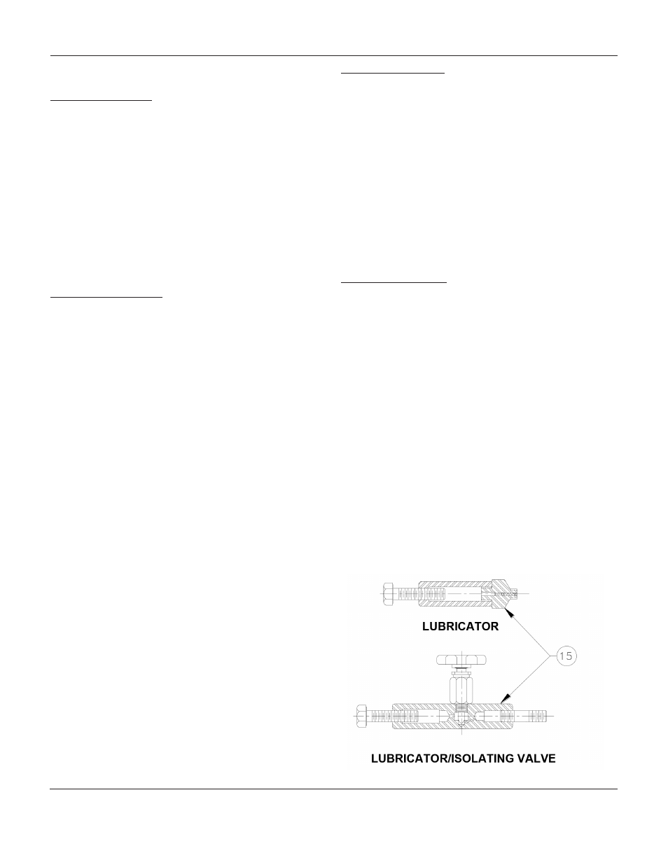
Packing Lubrication
The use of semi-metallic packing requires the use of
a lubricator or lubricator/isolating valve (figure 3). The
lubricator or lubricator/isolating valve is mounted in
place of a pipe plug (key 14, figure 6, 7). For standard
service up to 450
o
F, use Dow Corning lubricant or
equivalent.
Lubricator:
To add lubricant to the packing box, turn
the cap screw in a clockwise direction.
Lubricator/Isolating Valve:
Open the isolating valve,
turn the cap screw in a clockwise direction, then close
the isolating valve.
Lapping Metal Seats
In any valve body, a certain amount of leakage should
be expected with metal-to-metal seating. However, if
the leakage becomes excessive, lapping can enhance
the condition of the seating surfaces of the valve plug
and seat ring. Deep nicks in the seating surface should
be removed by machining rather than lapping. There
are many lapping compounds available commercially.
Be sure to use one of high quality. Apply lapping com-
pound to the bottom of the plug.
In order to position the cage and seat ring properly
and to help align the valve plug with the seat ring, bolt
the bonnet to the body with gaskets (the old gaskets
can be used) in place during the lapping procedure. A
simple handle can be made from a piece of metal se-
cured to the valve stem with nuts. Rotate the handle in
opposite directions to lap the seating surfaces. Once
lapping is complete, disconnect the bonnet, clean the
seating surfaces, reassemble and then test for shutoff.
If leakage is still excessive, repeat the lapping proce-
dure.
Figure 3: Lubricator and Lubricator/ Isolating Valve
Ma
rk
ED
anD
ET S
EriES
1-6
inch
G
lobE
S
TylE
c
onTrol
V
alVES