Valve disassembly, Maintenance, Packing replacement – Jordan Valve Mark 78 Series – Globe Style Control Valve User Manual
Page 2
3. After packing is installed, assemble packing follower
(11), packing nut (15) to bonnet (4).
Valve Disassembly
1. Close inlet and outlet stop valves. Operate system by-
pass if necessary.
2. Following instructions according to valve action:
3a. Direct Acting Actuator (ATC): shut off operating me-
dium and relieve pressure from diaphragm by discon-
necting tubing at diaphragm case. To remove the ac-
tuator from the valve body assembly: loosen the two
stem nuts (28) and move down the stem (9). Lock the
nuts together and, using a wrench on these nuts and
the flats on the stem connector (34), turn the valve
stem out of the stem connector threads until it dis-
engages. Loosen and remove the four yoke bolts (6)
and lift the actuator assembly from the bonnet (4).
3b. Reverse Acting Actuator (ATO): apply air pressure to
actuator to lift plug off of seat. To remove the actuator
from the valve body assembly: loosen and remove
the four yoke bolts (6) and lockwashers (8). Loosen
the two stem nuts (28) and move down the stem (9).
Lock the nuts together and, using a wrench on these
nuts and the flats on the stem connector (34), turn
the valve stem out of the actuator stem threads until it
disengages. Lift the actuator assembly from the bon-
net (4).
4. Loosen packing nut (15).
5. Remove bonnet (4), o-ring (29), compressor (5) and
cage (2) from the body (1).
6. Remove support washer (42) [on soft seated valves
in 1/2” – 3/4” sizes only], seal (41) [soft seated valves
only], seat (3), and seat o-ring (30) from the body.
7. Remove the two stem nuts (28) from the stem (9).
8. Remove plug/stem (9) from the bonnet (4).
9. Remove packing nut (15), packing follower (11) and
packing (13).
10. Cleaning: clean all parts with an approved, non-res-
idue-forming solvent. Remove encrusted materials
with crocus or very mild aluminum oxide cloth. Clean
packing box thoroughly.
11. Inspect all parts including plug, seal and seat. Re-
place any badly worn or damaged parts.
12. Replacing Seats (Hard Seated Valves Only): if seat is
badly worn or damaged, it should be replaced. Very
minor cuts on the seating surface, however, may be
lapped out. NEVER lap to the extent that the valve
plug becomes grooved.
13. Lapping in Valve Plug & Seat Ring: replace valve plug
(9) in bonnet (4). Apply superfine lapping compound
to valve plug seating surface at several points. Re-
place seat o-ring (30) and seat (3) in body (1). Re-
assemble bonnet (4) to body (1). Use stem to align
seat to plug in the body. Lap valve plug and seat ring
in until a fine continuous ring of contact has been
made on both surfaces. DO NOT lap until a ridge is
formed in valve plug seating face. A few turns are suf-
to start flow through the control valve. Increase flow
gradually by slowly opening the inlet shutoff valve. Do
not fully open the inlet valve until you are sure that
the controller and control valve have control of the
system. Usually, the handwheel on the inlet valve will
turn freely when this point is reached.
4. To shut off the line fluid, close the inlet shut-off valve
first, then the outlet shut-off valves.
Maintenance
To reduce maintenance time, refer to proper figure
and follow steps indicated below for applicable main-
tenance operation.
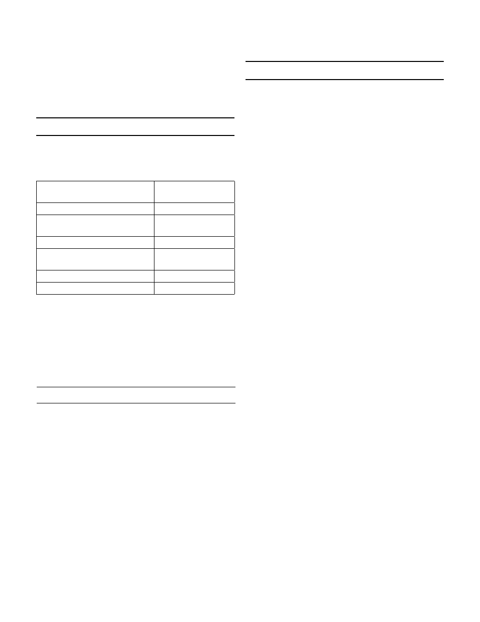
Proposed Maintenance
Procedure
Follow Steps...
Renewing stem packing
Packing Replacement
Valve disassembly, inspecting
parts, replacing plug or seat ring
Valve Disassembly
Valve Reassembly
Valve Reassembly
Actuator spring preload
adjustment
Actuator Spring
Preload Adjustment
Actuator maintenance
Actuator Maintenance
Changing valve action
Reversing Action
Routine maintenance should be expected due to nor-
mal wear and tear, damage from external sources or de-
bris. The regulator components, especially the moving
and sealing parts, should be inspected periodically and
replaced as necessary. Frequency of inspection/replace-
ment depends upon severity of conditions, but may also
be required by local/state/federal law or industry stan-
dards.
Packing Replacement
Renew valve plug stem packing if control valve has been
in service beyond normal maintenance, and packing
shows signs of wear. Wear will be indicated by leakage
which cannot be corrected by minor tightening of pack-
ing flange.
An additional packing ring can be installed to overcome
minor leakage without dismantling the control valve or
breaking valve plug connection.
1. Disassemble control valve as far as necessary for the
work required (see “Valve Disassembly”). Remove
packing. Clean valve plug stem (9) and packing box
thoroughly. Polish valve plug stem (9) with crocus
cloth. Use approved non-residue-forming solvent for
cleaning. Wipe dry with clean cloth.
2. Insert a new set of packing (13) in packing box. Press
each ring down in place with a tube as it is installed.
-2-