5 connecting to the public grid, Warning, Caution – KACO blueplanet 1502xi User Manual
Page 33: Action
Page 30
30
31000770-02-112609 blueplanet Operating and Installation Instructions 1502xi - 5002xi
ACTION
The ground for the DC input is provided by the integral
GFDI circuit. DC input should not be grounded external
to the unit.
Circuit board fuse
The power section has two internal circuit board fuses. These
are labelled F801 or F861 on the circuit board.
F801:
Model: 179120 5x20 time-lag 250VAC/0.4A
Manufacturer: SIBA
F861:
Model: TR5-Fuse series 372 250VAC/125VDC/1A time-lag
Manufacturer: Littlefuse/Wickmann
!
WARNING
For continued protection against risk of fire, replace
only with same type and ratings of fuse.
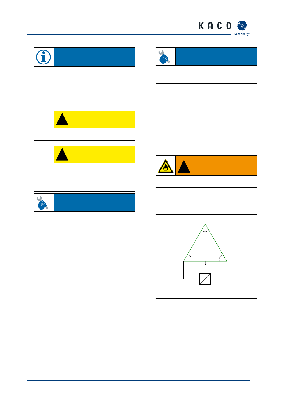
5.5 Connecting to the Public Grid
The inverter can be installed on the following grid-types:
L3
120°
L1
L2
120°
120°
=
~
240V
240V
N
120V
120V
Figure 5.11: 240 V Delta: 120 V Stinger
Country setting on the display: USA 240 V
NOTE
A screwdriver (slotted, 3.5 mm) is to be used for the terminals
in the inverter. Put the screwdriver into the intended cut-out.
Press the screwdriver upwards a bit. Put the cable into the
spring terminal. Put the screwdriver back into the original
position. Remove the screwdriver. The spring terminal is
closed and the cable is held in place. Lightly pull on the
wire to be sure it is secure.
!
CAUTION
Be sure the inverter is configured for the proper DC
grounding configuration of the system.
!
CAUTION
The voltage of the solar generator must be
measured before connecting the DC leads to the
inverter terminals. The DC voltage must not exceed
the max. generator voltage because this would
destroy the unit.
ACTION
Before connecting the PV generator to the blueplanet, check
that the PV generator is not grounded.
– Measure the DC voltage between the protective ground
(PG) and the positive lead and between the protective
ground (PG) and the negative lead of the PV generator.
– If stable voltages can be measured, this indicates a
ground fault in the PV generator or its wiring. The ratio
between the measured voltages gives an indication as to
the location of this fault. Rectify this fault before taking
any further measurements.
– Measure the electrical resistance between the protective
ground (PG) and the positive lead and between the
protective ground (PG) and the negative lead of the PV
generator.
– Low resistance (< 2 MΩ) indicates a high-impedance
ground fault of the PV generator, which must be fixed
prior to continuing with the installation.
Once the wiring in the connection box is installed the protective
cover over the terminals must be secured using the included
screws and must not be opened unless the switch is in the off
position, the AC breaker is in the off position, and the PV array
is powered down with an opaque cover or other equivalent
method to assure there is no DC voltage present in the box.
The connection box should be considered the same as any
other external DC disconnect switch which has live conductors
inside.
Section 5 ·
Installation and Start-Up