Laney, Pin 1 = gnd pin 2 = hot pin 3 = cold, Operating instructions – Laney A1 User Manual
Page 8: Input/output jacks
O
N
M
UTE
2
P
HASE
1
D.I.
1
A
COUSTIC
A
MPLIFIER
A1
P
OWER
0
E
NHANCE
B
ASS
B
ASS
F
REQUENCY
L
EVEL
T
REBLE
N
OTCH
M
ASTER
B
RILLIANCE
V
OLUME
T
REBLE
M
UTE
CD I
N
V
OLUME
V
OLUME
L
EVEL
H
I
Z
O
N
M
ID
A
CTIVE
E
FFECT
1
2
M
IC
P
AD
I
NSTRUMENT
O
N
C
OMP
G
AIN
1
FRONT PANEL CONTROLS - continued
20
Laney
OPERATING INSTRUCTIONS
Laney
OPERATING INSTRUCTIONS
Page 8 /16
Page 9 /16
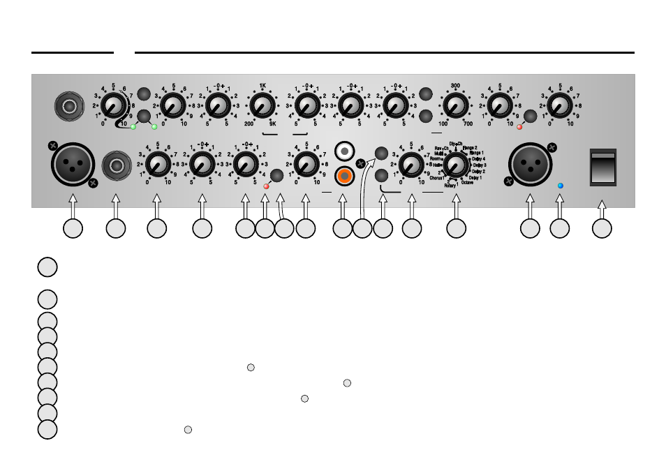
Balanced input provided for connecting an XLR equipped input such as a low impedance microphone ( 200-600 Ohms) or a
DI’d guitar etc.
Input provided for connecting high impedance microphones or sources that require a high impedance connection and are
fitted with a 1/4” jack - such as an additional guitar, bass or drum machine.
Sets the volume of the instrument(s) plugged into channel 2.
Sets the bass response for whatever is connected to channel 2.
Sets the treble response for whatever is connected to channel 2.
Led is lit when channel 2 is muted (with )
Mutes whatever instrument is connected into channel 2. Led is lit when muted.
Sets the volume of what ever source is plugged into (Channel 3)
RCA/Phono connections provided for connecting an external sound source such as a CD, Mini Disc or MP3 player etc.
Assigns the chosen effect ( ) to channel 1.
26
25
28
32
20
21
22
23
24 25 26 27
28
30
31
32
33
34
35
21
22
23
24
25
26
27
28
29
29
30
1
Assigns the chosen effect ( ) to channel 2.
Sets the level from the onboard digital effects section, present in the overall mix.
The onboard digital effects have been custom designed by Laney to complement the A1. You have a choice of delays, flange,
rotary, octave, chorus, reverb and combinations of these. Select the chosen effect here, and set the level with
This XLR socket provides a low impedance output for direct injection of the amplifier signal to a mixing desk or power
amplifier. It is taken after the main mix stage, but prior to the main volume control.
When ‘on’ Indicates that power is connected to the unit and it is ready to go.
(Always switch off and disconnect the power cord when not in use)
Main power switch for the unit.
32
31
31
32
33
34
35
FRONT PANEL CONTROLS - continued
PIN CONNECTIONS
11
22
33
Mic in XLR
Mic in XLR
DI Out XLR
DI Out XLR
11
22
33
Pin 1 = Gnd
Pin 2 = Hot
Pin 3 = Cold
Pin 1 = Gnd
Pin 2 = Hot
Pin 3 = Cold
11 22
Input/Output Jacks
Input/Output Jacks