Laney AH40 User Manual
Page 11
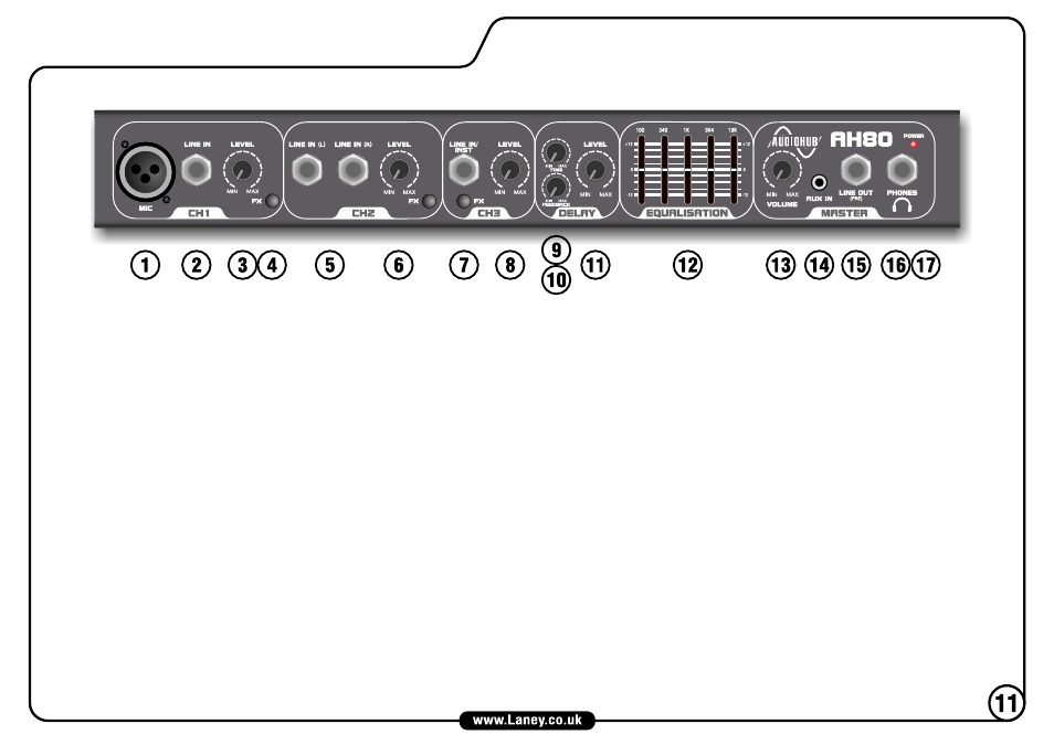
AH80 FRONT PANEL
1. CH1 MIC INPUT Balanced XLR input for low impedance microphone signals (200-600 Ohms).
2. CH1 LINE INPUT Unbalanced Jack input socket for connection of all line level signals (keyboard, signal processor, sample, drum machine, etc.). Note that the Mic
and Line inputs may be used simultaneously, although it may be difficult to balance input levels, depending on your source.
3. CH1 LEVEL Adjusts the channel level, enabling the user to balance levels across channels.
4. FX SEND When pushed in, this switch routes the channel signal to the built in digital delay.
5. CH2 STEREO LINE INPUT 2 x Unbalanced Jack sockets for connection of a stereo line signal. Sockets may also be used to connect a single mono source, or two
individual sources. When connecting independent sources, use the output controls on your device to adjust the balance between the two signals.
6. CH2 LEVEL & FX See CH 1 LEVEL & FX.
7. CH3 LINE/INSTRUMENT INPUT Unbalanced high impedance input for connection of high impedance devices such as electric guitars/basses, or regular line
devices. This channel features +6dB gain compared to the other line inputs, so take care if connecting a line level device here.
8. CH3 LEVEL & FX See CH1 LEVEL & FX. As this channel has more gain than the other line inputs, don’t be surprised if you find that you need to set this control
lower than the others when using line level devices.
9. DELAY TIME Controls the amount of time between repeats of the inbuilt delay. Turning this control clockwise will increase the delay time.
10. DELAY FEEDBACK This controls the amount of repeats in the inbuilt delay. Turning the control clockwise increases the amount of repeats.
11. DELAY LEVEL Controls the mix level of the inbuilt delay. Use the delay to add atmosphere to your sound, or to create interesting effects.
12. GRAPHIC EQ A 5-Band graphic equaliser to fine tune your sound and help eliminate feedback issues. This is applied to the master mix. EQ is best used subtly.
Cutting or boosting all bands, or using extreme settings can reduce clarity and dynamics.
13. MASTER VOLUME Sets the overall output level of the amplifier or headphones.
14. AUX INPUT 3.5mm Stereo Jack for connection of an auxiliary source such as an MP3 player. This input is controlled by the master volume control. The graphic
equaliser has no effect on the Aux input.
15. LINE OUT Balanced line output for recording or connection to another amplifier. This output is not affected by the equaliser or master volume. The Aux input does
not appear on this output. This allows you to record your performance without the presence of a backing track.
16. PHONES Stereo headphone socket. This disconnects the internal speaker so that you can practice by yourself. Ensure that the Master Volume is turned down
before plugging in your headphones.
17. POWER LED Indicates that the unit is powered on.