Chapter 2, System components, Front components – Lanner LVC-2000 User Manual
Page 9
Advertising
9
System Components
Chapter 2
Embedded and Industrial Computing
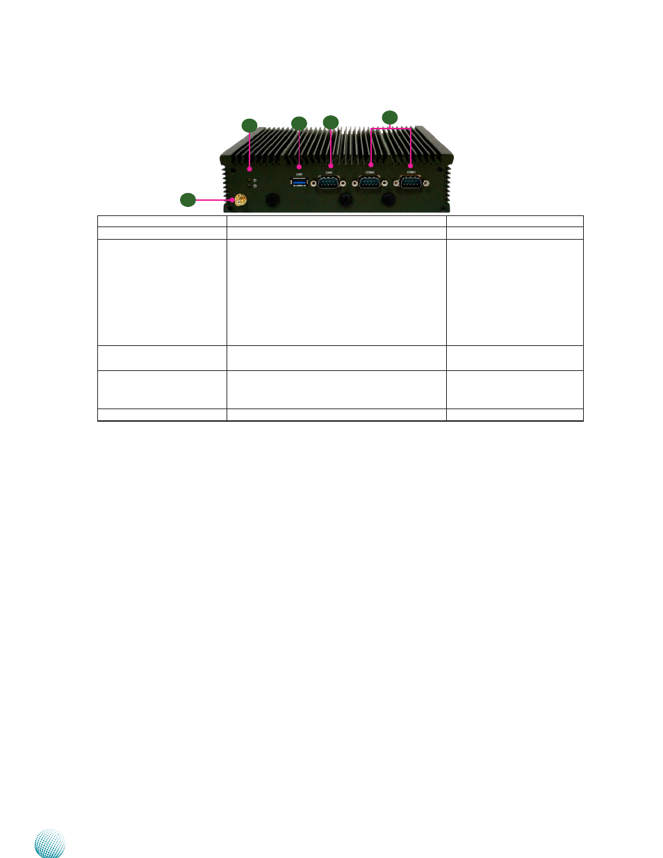
Component
Description
Pin Definition Reference
F1 GPS Antenna
Reserved for GPS antenna
F2 HDD/SSD and
Power LED (Green)
HDD/SSD
•
Blinking: means data access activities
•
Off: means no data access activities or no
hard disk present
Power
•
On: The computer is on.
•
Off: The computer is off .
F3 USB 3.0 Ports
USB 3.0 type A connectors. There are additional
2 USB 2.0 ports with pin headers
USB2 on page
F4 CAN bus
CAN bus connector for controller area network
communication. It supports J1939 &J1708
standards.
CAN1 on page
F5 COM1/COM2
RS232 ports for serial communication
COM1/COM2 on page
Front Components
F1
F2
F3
F4
F5
Advertising