3 connectors pin assignment – Lanner FW-8892 User Manual
Page 17
FW-8892
17
2.1.3 Connectors Pin Assignment
z
Ethernet Interface
Part reference:
LANB2
Bellow shows the pin assignment of the RJ45 connector for Ethernet
LANB2 (For IPMI)
PIN
DESCRIPTION
1 A_ETH_TXP
2 A_ETH_TXN
3 A_ETH_RXP
4 ETH_SPEED
5 ETH_LINK
6 A_ETH_RXN
7 FP_LAN_RST_N
8 GND
9 NC
10 NC
11 NC
12 NC
z
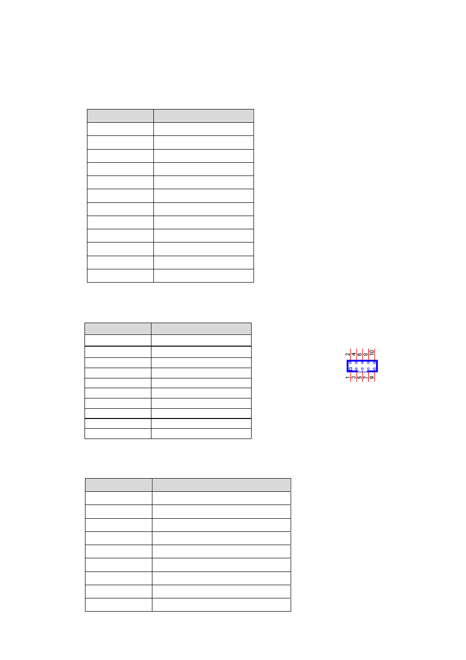
USB Interface
Part reference: USBA1 (To Front Panel); USBA2 (To Pin Header);
Bellow shows the pin assignment of the USB connector.
PIN
DESCRIPTION
1 VCC
2
VCC
3 USB_L_2N
4 USB_L_1N
5 USB_L_2P
6 USB_L_1P
7 GND
8 GND
9 GND
10 GND
z
COM port interface
Part reference: COM1; COM2
Bellow shows the pin assignment of the COM port connector.
PIN
DESCRIPTION
1
Data Carrier Detect : DCD
2
Received Data : SIN
3
Transmitted Data : SOUT
4
Data Terminal Ready : DTR
5
Signal Ground : GND
6
Data Set Ready : DSR
7
Request To Send : RTS
8
Clear To Send : CTS
9
Ring In : RI