Connection panels – beovision 10-40/46 – Bang & Olufsen BeoVision 10 Getting Started User Manual
Page 24
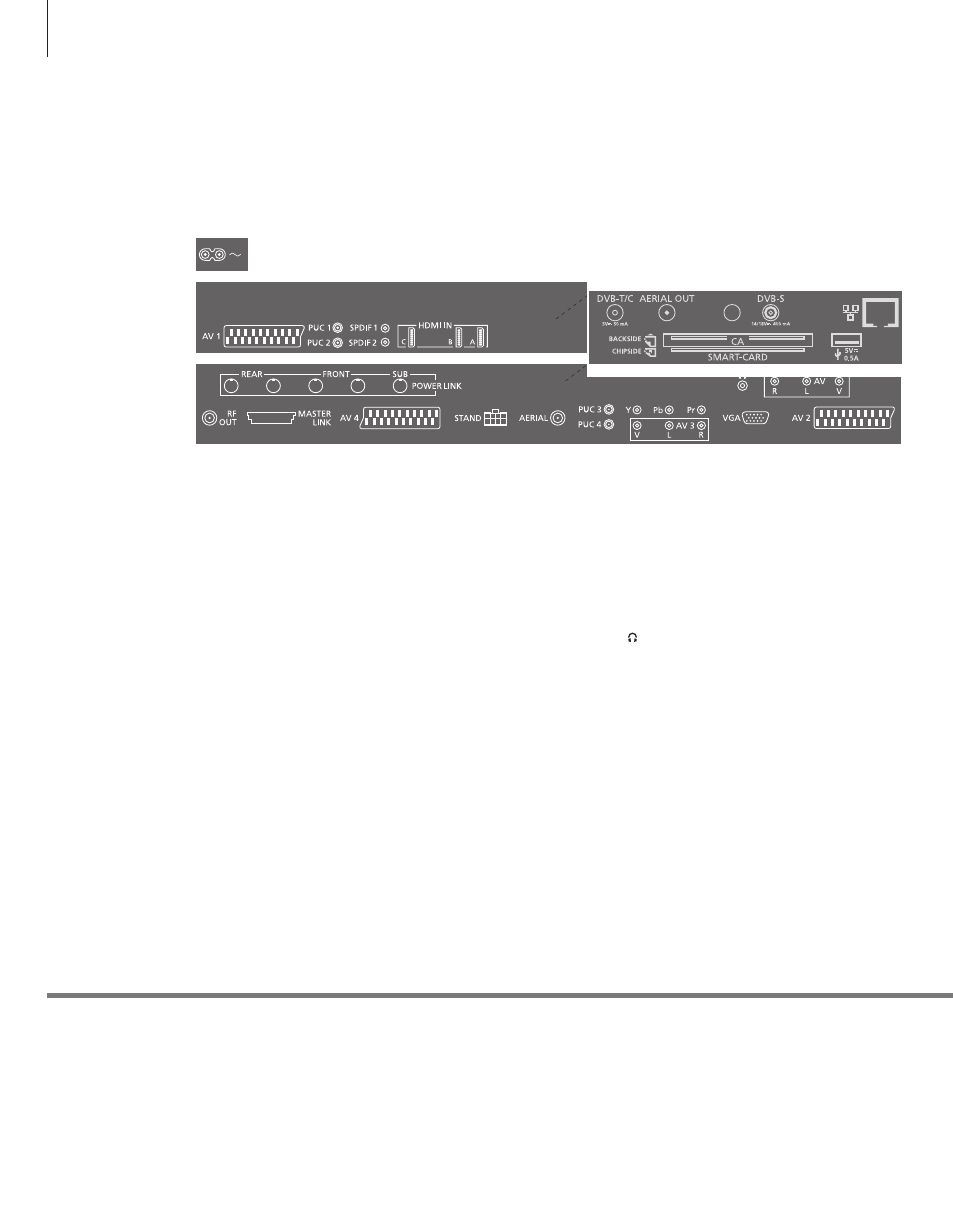
Connection panels – BeoVision 10-40/46
~ – Mains supply
Connection to the mains supply.
AV (1–2 and 4)
21-pin sockets for connection of additional video
equipment, such as a DVD player, set-top box,
a decoder or video recorder.
PUC (1–4)
For IR control signals to external equipment
connected to an AV socket.
SPDIF (1–2)
Digital audio input socket, e.g. DVD player. You
can use the socket in conjunction with an AV
socket.
HDMI IN (A–B, and C on some models)
For High Definition Multimedia Interface video
source or PC. The sources can be registered to any
of the AV socket groups. To expand the number
of HDMI sockets, connect an HDMI Expander to
the HDMI C socket, when available, otherwise to
the HDMI B socket.
POWER LINK (FRONT – REAR)
Use for connection of external loudspeakers in a
surround sound setup. See the Guide for further
information.
POWER LINK (SUB)
Use for connection of a Bang & Olufsen subwoofer.
RF OUT
Aerial output socket for distribution of video
signals to other rooms. Also requires an RF Link
Amplifier. See the Guide for further information.
MASTER LINK
For a compatible Bang & Olufsen audio or video
system.
STAND
For connection of a motorised stand.
AERIAL
Aerial input socket for an analogue TV signal.
Y – Pb – Pr (AV2–4, 6)
For video signals from an external source,
e.g. HDTV source. You can use the socket in
conjunction with an AV socket or a digital audio
socket.
AV3 (video, L, R)
For audio connection (right and left sound
channel respectively) and video signals from an
external source.
VGA (AV3)
For connection of a PC to receive analogue
graphics.
CAMERA (R, L, video, AV5)
For audio connection (right and left sound
channel respectively) and video signals from an
external source.
Connect stereo headphones.
Note: Prolonged listening at high volume levels
can cause hearing damage!
1
*DVB
Mains cord and plug
Use a camera or headphones
The number and types of DVB sockets depend on which optional DVB module is installed in the television.
Connect the ~ socket on the main connection panel of your TV to the wall outlet. The TV is in standby
mode and ready to be used.
See the Guide for information about use of camera and headphones.
CAMERA
5
24
Any equipment you connect to the main connection panel must be registered in the
‘CONNECTIONS’ menu.
Mains supply