Antenna considerations, Power control – Linx Technologies RXM-GPS-R4 User Manual
Page 7
–
–
–
–
8
9
Antenna Considerations
The R4 Series module is designed to utilize a wide variety of external
antennas. The module has a regulated power output which simplifies
the use of GPS antenna styles which require external power. This allows
the designer great flexibility, but care must be taken in antenna selection
to ensure optimum performance. For example, a handheld device may
be used in many varying orientations so an antenna element with a wide
and uniform pattern may yield better overall performance than an antenna
element with high gain and a correspondingly narrower beam. Conversely,
an antenna mounted in a fixed and predictable manner may benefit from
pattern and gain characteristics suited to that application. Evaluating
multiple antenna solutions in real-world situations is a good way to rapidly
assess which will best meet the needs of your application.
For GPS, the antenna should have good right hand circular polarization
characteristics (RHCP) to match the polarization of the GPS signals.
Ceramic patches are the most commonly used style of antenna, but
there are many different shapes, sizes and styles of antennas available.
Regardless of the construction, they will generally be either passive or
active types. Passive antennas are simply an antenna tuned to the correct
frequency. Active antennas add a Low Noise Amplifier (LNA) after the
antenna and before the module to amplify the weak GPS satellite signals.
For active antennas, a 300 ohm ferrite bead can be used to connect the
VOUT line to the RFIN line. This bead prevents the RF from getting into the
power supply, but allows the DC voltage onto the RF trace to feed into the
antenna. A series capacitor inside the module prevents this DC voltage
from affecting the bias on the module’s internal LNA. The VOUT line is
connected to the VCC line, so the voltage is the module supply voltage and
the current sourcing depends on the module’s power supply.
Maintaining a 50 ohm path between the module and antenna is critical.
Errors in layout can significantly impact the module’s performance. Please
review the layout guidelines elsewhere in this guide carefully to become
more familiar with these considerations.
Power Control
The R4 Series GPS Receiver module offers two power control modes: Full
Power and Hibernate. In Full Power mode the module is fully active and
and continuously tracking. Measurements are of the highest quality and are
continuously output by the module. This is the highest current consumption
state.
Hibernate mode is the lowest power setting. The tracking and processor
blocks are powered down, but the RTC is still running and the memory
blocks are still powered enabling a hot start.
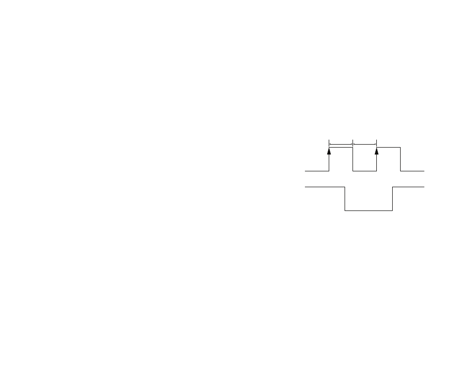
The module switches between these states by toggling the ON_OFF line.
The ON_OFF line must go high for at least 100ms to trigger the change of
state and must remain low for at least 100ms to reset the edge detector.
If the module is in Full Power mode, a pulse on the ON_OFF line will initiate
an orderly shutdown into Hibernate mode. If the module is in Hibernate
mode, a pulse on the ON_OFF line will transistion the module into Full
Power Mode.
ON_OFF
Full Power
Hibernate
Full Power
Module
Power
100ms
100ms
Figure 7: R4 Series GPS Receiver Power Control