Ordering information, Electrical specifications, Electrical specifications ordering information – Linx Technologies RXM-xxx-ES User Manual
Page 4
– –
– –
2
3
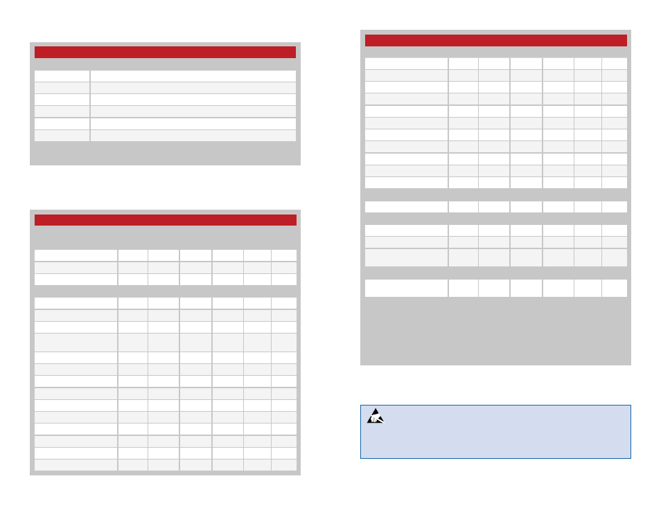
ES Series Receiver Specifications
Parameter
Symbol
Min.
Typ.
Max.
Units
Notes
Power Supply
Operating Voltage
V
CC
4.5
5.0
5.5
VDC
Supply Current
I
CC
5.5
6.0
6.5
mA
Power-Down Current
I
PDN
50.0
µA
4
Receiver Section
Receive Frequency
F
C
RXM-869-ES
869.85
MHz
RXM-916-ES
916.48
MHz
Center Frequency
Accuracy
–60
+60
kHz
LO Frequency
RXM-869-ES
859.15
MHz
RXM-916-ES
905.78
MHz
IF Frequency
F
IF
10.7
MHz
Spurious Emissions
–75
–50
dBm
1
Receiver Sensitivity
–92
–97
–102
dBm
2
Noise Bandwidth
N
3dB
280
kHz
Audio Bandwidth
20
28,000
Hz
3,4
Audio Output Level
360
mV
P-P
4,5
Data Rate
200
56,000
bps
4
Electrical Specifications
Ordering Information
Ordering Information
Part Number
Description
TXM-869-ES
ES Series Transmitter 869MHz
TXM-916-ES
ES Series Transmitter 916MHz
RXM-869-ES
ES Series Receiver 869MHz
RXM-916-ES
ES Series Receiver 916MHz
EVAL-***-ES
Basic Evaluation Kit
MDEV-***-ES
Master Development System
*** = Frequency
Receivers are supplied in tubes of 40 pcs.
Figure 2: Ordering Information
ES Series Receiver Specifications
Parameter
Symbol
Min.
Typ.
Max.
Units
Notes
Data Output
Logic Low
V
OL
0.0
0.1
VDC
Logic High
V
OH
V
CC
– 1.1
V
CC
– 1
V
CC
– 0.9
VDC
Power Down Input
Logic Low
V
OL
0.0
0.8
VDC
Logic High
V
OH
2.8
V
CC
VDC
RSSI
Dynamic Range
60
dB
4
Gain
30
mV/dB
4
Voltage with No Carrier
1.1
V
4
Voltage with No Carrier
2.9
V
4
Antenna Port
RF Input Impedance
R
IN
50
Ω
4
Timing
Receiver Turn-On Time
Via V
CC
3.8
4.7
5.4
mS
4,6
Max Time Between
Transitions
0
5.0
mS
4,7
Environmental
Operating Temperature
Range
0
+70
ºC
4
1. Into a 50-ohm load.
2. For 10
-5
BER at 9,600 baud.
3. The audio bandwidth is wide to
accommodate the needs of the data
slicer. In audio applications, audio
quality may be improved by using
a low-pass filter rolling off at the
maximum frequency of interest.
4. Characterized, but not tested.
5. Input frequency deviation-dependent.
6. Time to receiver readiness from the
application of power to V
CC
or PDN
going high.
7. Maximum time without a data
transition.
Figure 3: Electrical Specifications
Warning:
This product incorporates numerous static-sensitive
components. Always wear an ESD wrist strap and observe proper ESD
handling procedures when working with this device. Failure to observe
this precaution may result in module damage or failure.