Using the rssi line, Using the es for digital applications – Linx Technologies RXM-xxx-ES User Manual
Page 8
– –
– –
10
11
Using the RSSI Line
The receiver’s Received Signal Strength Indicator (RSSI) line serves a
variety of uses. The RSSI line has a dynamic range of 60dB (typical) and
outputs a voltage proportional to the incoming signal strength. A graph of
the RSSI line’s characteristics appears in the Typical Performance Graphs
section. The RSSI levels and dynamic range vary slightly from part to part.
It is important to remember that the RSSI output indicates the strength
of any in-band RF energy and not necessarily just that from the intended
transmitter; therefore, it should only be used to qualify the level and
presence of a signal.
The RSSI output can be used to create external squelch circuits. It can be
utilized during testing or even as a product feature to assess interference
and channel quality by looking at the voltage level with all intended
transmitters off. The RSSI output can also be used in direction-finding
applications although there are many potential perils to consider in such
systems. Finally, it can be used to save system power by “waking up”
external circuitry when a transmission is received or crosses a certain
threshold. The RSSI output feature adds tremendous versatility for the
creative designer.
Using the ES Series Receiver for Analog Applications
The ES Series is an excellent choice for sending a wide range of analog
information, including audio. The ability of the ES to receive combinations
of analog and digital signals also opens new areas of opportunity for
creative product design.
The AUDIO line should be buffered and filtered to obtain maximum
signal quality. This is particularly important because the audio output is
AC-coupled and any DC loading causes errors in the data slicer since data
is derived from the audio voltage. For voice, a 3–4kHz low-pass filter is
often employed. For broader-range sources, such as music, a 12–20kHz
cutoff is more appropriate. When only sending audio, the DATA line should
be pulled to V
CC
to reduce noise resulting from the data slicer switching.
The Signal-to-Noise Ratio (SNR) of the audio depends on the bandwidth
selected. The higher the SNR, the less hiss there is in the background. For
the best SNR, choose the lowest filter cutoff appropriate for the intended
signal. For applications that require true high fidelity, audio RF links
designed expressly for this purpose may prove to be a more appropriate
solution; however, a compandor may also be used with the ES Series
transmitter to provide further SNR improvements.
The 360mV
P-P
output level of the AUDIO line is not sufficient to drive a
speaker, so an amplifier is required. This amplifier can also be used to
provide the buffering and filtering described above. Some manufacturers
make amplifiers specifically for audio applications, but standard filter
designs, such as Butterworth or Sallen-Key, can also be used.
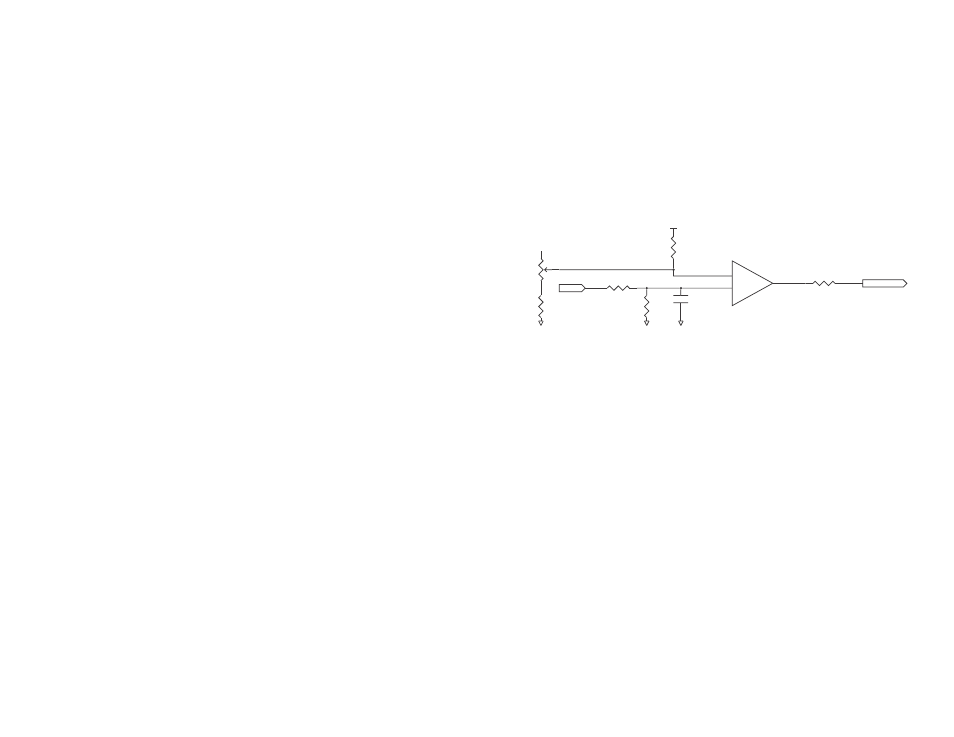
To avoid audible white noise or hiss when no transmission is present,
a squelch circuit can be implemented to provide muting. This is easily
accomplished with a circuit like the one shown in Figure 12.
Squelching is implemented by comparing the RSSI voltage to a voltage
reference (typically a voltage divider) with an open collector-style
comparator. When the RSSI voltage becomes lower than the voltage
reference, the comparator output is pulled to ground, disabling the AUDIO
output. This is useful because the analog circuit can be disabled either
when the receiver is out of range or the transmitter is turned off. Of course
it is the designer’s responsibility to choose a squelch topology that best fits
the specific needs of the product.
Using the ES for Digital Applications
As previously discussed, it is important to note that this receiver does not
provide hysteresis or squelching of the DATA line. This means that in the
absence of a valid transmission or transitional data, the DATA line switches
randomly. In many applications this hash is ignored by the decoder or
system software, but, depending on your application, it may be useful to
add an external circuit to provide data squelching and hysteresis.
A squelch circuit disables the DATA output when the RSSI voltage falls
below a reference level. Hysteresis makes the RSSI voltage have to fall
lower than the reference voltage before switching off, and to have to rise
5k
POT
RSSI
GND
GND
GND
VCC
LM393
–
+
0.01uF
39k
10k
2M
39k
AUDIO REF
10-20k
Figure 12: ES Series Receiver Squelch Circuit