The transcoder area, The usb area, The power supply – Linx Technologies MDEV-LICAL-MT User Manual
Page 6
–
–
–
–
6
7
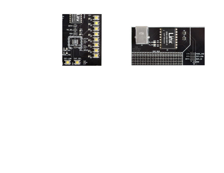
The Transcoder Area
The transcoder is placed in the center
of the chain logo. To the right are two
function switches. SEL_BAUD sets the
baud rate of the transcoder. If the switch
is up, the baud rate is 28,800bps; if down,
the baud rate is 9,600bps. *Important*
Both transcoders must be set to the same
baud rate. The on-board transceiver is
only capable of operation at 9,600bps.
If the LATCH switch is up, then the status
lines are latched. If the switch is down,
then the status lines are momentary.
To the right of the function switches are a
column of status line LEDs and a column
of status line buttons. Each status line has one LED and one button, so
button S0 and LED D0 correspond to status line D0; S1 and D1 to line D1
and so forth. Pressing a button takes the status line high when the line is
set as an input. The LED activates when a line set as an output goes high.
There is no isolation between the LEDs and the buttons, so pressing the
button for a status line input also activates the LED. Resistors provide short
circuit protection if a button is pressed for an output line that is pulled low.
Beneath the transcoder are two LEDs. D8 is connected to the MODE_IND
line and lights up as described in the MT Transcoder Data Guide. D9
is connected to the CONFIRM line and lights up when the transcoder
receives a valid confirmation from a remote unit.
Beneath the LEDs is a button that is connected to the CRT/LRN line. This
button is used to create the Address, set the Control Permissions, and
learn an address as described in the MT Series Transcoder Data Guide.
Next to the CRT/LRN button is a button connected to the ENC_SEL line.
This button is used with the CRT/LRN button to create the Address and
set the Control Permissions. Next to the button is a switch that takes the
ENC_SEL line high so that the transcoder can be placed into Encoder Only
mode. If the switch is up, then the line is controlled by the button. If the
switch is down, then the line is connected to V
CC
.
Figure 6: The Transcoder Area
The USB Area
The development boards have a Linx SDM-USB-QS-S module for use with
a PC. This module is powered by the USB bus so no current is drawn from
the battery.
The jumpers to the right connect the USB module to the transcoder when
the USB interface is in use and should be disconnected when not in use.
U4 is a switch that connects the SER_IO line on the transcoder to either
the RXD or TXD lines on the USB module based on the state of the RTS
line. U5 is a level translator that converts the 5V signals from the USB
module to 3V for the transcoder and vice versa. The RX_IND LED to the left
of the module will flash when data is being received from the PC, and the
TX_IND line will flash when the module is sending data to the PC.
The Power Supply
The power supply consists of a standard 9V battery and a power
jack connected to a 3.0V voltage regulator. The regulator can provide
approximately 500mA of current to the prototyping area. If the added
circuitry needs more than this, then the designer must add an external
supply. If the circuit consistently draws more than 100mA of current, it
might be better to use the power jack, as the battery may run down fairly
quickly, reducing testing and development time.
The jack accepts a standard 5.5mm plug with the tip ground and the outer
shell 7 to 16VDC positive supply. A reverse voltage protection diode is
included on the board to protect the circuitry in case the voltage on the
plug is reversed, but it is still a good idea to double-check the polarity.
Figure 7: The USB Area